background image

   INTRODUCTION  

© WASP S.r.l. 

4

43

Preparing to use the printer

4

5.3. First start 

After having correctly connected the printer to the socket it is necessary to perform some operations in order to 
allow the printer to work.

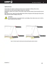
Belt-stop clamps

Inside the printer there are three belts necessary for moving the extruder during printing.
To avoid movements of the extruder during transport, clamps are applied on the straps, this have to be removed 
before starting the print.

Summary of Contents for 4070 ZX

Page 1: ...MANUAL OF USE AND MAINTANANCE ORIGINAL INSTRUCTIONS WASP4070ZX...

Page 2: ...o achieve the best results from WASP 4070 ZX No part of this publication may be reproduced stored in a filing system or transmitted to third parties in any form or by any means without the Manufacture...

Page 3: ...ttings 38 5 2 6 GCODE 39 5 2 7 PRINTING board 40 5 2 8 TUNE menu 41 5 2 9 Digit window 42 5 3 First start 43 6 First use of the printer 44 6 1 General warnings 44 6 2 Preparing the 3D file 44 6 3 Slic...

Page 4: ......

Page 5: ...must always be available for consultation in copy and by the recipient on the printer itself or in its immediate vicinity In the second case the location of the manula must me indicated on the printe...

Page 6: ...is mandatory to keep this manual and all attached documents in an easily accessible place near the printer and known to all users operators and maintenance personnel Operators and maintenance technici...

Page 7: ...3dwasp com www 3dwasp com 1 2 Indentification label The printer is CE marked and complies with all relevant provisions Machinery Directive 2006 42 EC EMC Directive 2014 30 EU and LVD Directive 2014 3...

Page 8: ...oval of defects under warranty are the responsibility of the Manufacturer except in cases where the nature of the defect is such that it can be easily removed on site by part of the Customer All consu...

Page 9: ...on the printer can include Mechanical Electrical MECHANICAL NATURE INTERVENTIONS Any intervention of a mechanical nature must be carried out in strict compliance with the directives required by curre...

Page 10: ...ms are present as a standard in all machines and shall not for any reason be manipulated nor damaged Upon seeing abnormalities in the fuctions of these systems the user is responsible of reporting the...

Page 11: ...r Maintanance Cleaning Maintenance cleaning operations must be carried out by trained and authorized personnel Operations must be performed in a safe stop condition disconnecting the printer from powe...

Page 12: ...ntrusted to him who has responsibility for the job Below is a description of the professional profiles for the operators involved in the printer User Qualified personnel able to perform simple tasks t...

Page 13: ...n which there is the possibility of causing damage to the environment NOTE Indicate the notes warnings suggestions and other points on which you want to draw the reader s attention or complete the exp...

Page 14: ...INTRODUCTION WASP S r l 1 14 1...

Page 15: ...e and a pair of spool holders The material is unrolled from the spool pushed to the heated nozzle where it melts and is extruded through a nozzle that lays very small amounts of material starting from...

Page 16: ...status of the printer allowing a quick visualization LED color State Situations Green Operational Machine turned on and ready to operate or print concluded White Printing Machine busy in a printing pr...

Page 17: ...scription of the printer 2 Fig 2 2 Work area 2 2 Work area Legend 1 Cable carrier 2 Door handle 3 Carbon fiber rods 4 Zen X Extruder 5 Hepa filters 6 Chamber heaters 7 Sliders 8 VACS Vacuum Active Con...

Page 18: ...f the printer 2 Fig 2 3 External area of the printer 2 3 External area of the printer Legend 1 Ethernet door for static IP cable connection 2 Left and right filament drivers 3 Power socket 4 TFT touch...

Page 19: ...S r l 2 19 Description of the printer 2 2 4 Material storage area Legend 1 Left nozzle filament inlet 2 Right nozzle filament inlet 3 Right nozzle spool holder 4 Left nozzle spool holder Fig 2 4 Mate...

Page 20: ...DUCTION WASP S r l 2 20 Description of the printer 2 Fig 2 5 VACS Vaacum active control system 2 5 VACS Vacuum Active Control System Legend 1 Aluminum vacuum bed 2 Silicon gasket 3 Removable printing...

Page 21: ...220 240 V 50 60 Hz Absorbed power Extruder max 120W Heated bed max 1300 W Heated chamber max 1500 W Use features Environment of use 20 30 C Warehouse 0 30 C Nozzle max 350 C Heated bed max 120 C Heat...

Page 22: ...ionsotherthanthoseforwhichitwasdesignedandconstructeddescribed in paragraph 2 6 Failure to comply with safety regulations Operation of the printer with procedures other than those described in this ma...

Page 23: ...s the operator must wear all the necessary Personal Protective Equipment PPE 3 1 1 Delivery of the printer Upon receipt make sure that The printer has not been damaged during transport Any packaging h...

Page 24: ...urer ATTENTION Theweightoftheprinterisshowninparagraph2 4 Technicaldata Itisthereforenecessarytouse the lifting equipment whose expected flow is adequate for the weight to be lifted ATTENTION As long...

Page 25: ...to damage them Remember that the original packaging of the machine is to be conserved for the entire life cycle of the product When this operation is completed the machine will be laying on the base p...

Page 26: ...e operators1 and 2 will push the machine from its top in horizontal direction until it overhangs about 30 cm from the pallet fig 3 2c Using the two handles positioned on the top of the machine the ope...

Page 27: ...chine The operator 3 will guide the machine on the other side helping the edge to gently lay on the ground fig 3 2e Using the two handles positioned on the top of the machine the operators 1 and 2 wil...

Page 28: ...r3willhelpthemachinetogentlylayontheground In this phase is especially important paying attention to the feet fig 3 2g Now the machine is standing Move it on the floor by pushing in 2 people Ifthemach...

Page 29: ...ault on the machines Assemble the wheels on the bottom of the machine during the phase showed in fig 3 2b using the screws included Notice that one of the wheels is provided without brake this has to...

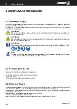
Page 30: ...INTRODUCTION WASP S r l 4 30 Description of the printer 4...

Page 31: ...necessary to prepare the necessary operating space by referring to the dimensions expressed in mm given in paragraph 2 4 Technical data The room must also be Equipped with the appropriate power supply...

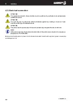
Page 32: ...cally against any crushing or sources of wear according to the type of installation made ATTENTION The printer must be powered by a 10A socket protected by a magnetothermic set at 30 mA NOTE All the d...

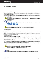
Page 33: ...ents of paragraph 1 6 General safety warnings Furthermore the specific requirements for safe interaction with the printer related to this chapter are detailed in the following paragraphs ATTENTION The...

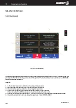
Page 34: ...d 1 Left extruder temperature click to set new target temperature 2 Right extruder temperature click to set new target temperature 3 Heated bed temperature click to set new target temperature 4 Wifi c...

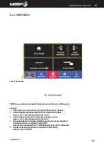
Page 35: ...from the selected extruder see par 6 5 Loading unloading the filament 3 Load material loads material inside the selected extruder see par 6 5 Loading unloading the filament 4 Vacuum Enables or disable...

Page 36: ...e PREPARE button in the toolbar Legend Free Zeta system enters in Free Zeta System Learn more in paragraph 8 6 Free Zeta System Disable motors disables all stepper motors on the machine Autocalibratio...

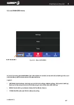
Page 37: ...dinarely with the instructions of the Manufacturer Legend SETTINGS Delta Settings Continuous print Extruder settings Motion settings Temperature settings Bed touch Filament sensor Out of Plate Blockin...

Page 38: ...arn more in paragraph 8 9 Network and printing server Legend 1 SSID to chose the desired network between all visible ones Static IP aption available with cable 2 PWD Allows to insert a password if pre...

Page 39: ...ng GCODE you can launch gcodes and moving them from the USB to the printer The gcodes are loaded in the machine as explained in detail in paragraph 8 7 Loading gcode Legend 1 Chose to navigate USB Dri...

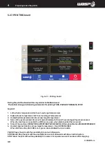
Page 40: ...stimated print time left percentage of layers processed When the machine is connected the WIFI icon is green when disconnected the icon is red 5 State of the machine OPERATIONAL PRINTING PAUSE CANCELL...

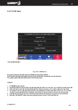
Page 41: ...ftheprocess standardis100 totuneituse and buttonandwait3seconds 3 Flow defines the amount of the flow standard is 100 to tune use and button and wait 3 seconds 4 Fan allows to set an user defined valu...

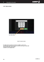
Page 42: ...reparing to use the printer 4 5 2 9 Digit window The digit window is used when is necessary to define a numeric value Use the button to digit the desired value and confirm with the green button SET Us...

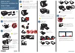
Page 43: ...ocket it is necessary to perform some operations in order to allow the printer to work Belt stop clamps Inside the printer there are three belts necessary for moving the extruder during printing To av...

Page 44: ...Equipment PPE NOTE Visit the website www 3dwasp com en download for the updated printing profiles user manuals and useful resources for the use of the machine 6 2 Preparing the 3D file Make sure that...

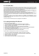
Page 45: ...ppearonthedisplay whichwillmakesuretocleanthebedandtheextruder itwillstarttheprocedure that will last a few minutes Learn more on the Autocalibration procedure on paragraph 8 2 Autocalibration 6 5 Loa...

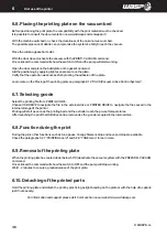
Page 46: ...cting gcode Select the printing file from PRINT GCODE Choose USB DRIVE to navigate the file in the external drive or PRINTER DRIVE to navigate the files saved in the internal storage of the printer Pr...

Page 47: ...c requirements for safe interaction with the printer related to this chapter are detailed in the following paragraphs ATTENTION The operations related to these activities must be performed by authoriz...

Page 48: ...manual ATTENTION The maintenance operations must be carried out by disconnecting the printer from the power source by unplugging the power plug NOTE In case of replacement of components during mainte...

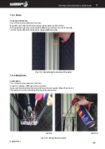
Page 49: ...perceive an important difference in tension on one of the belts contact the Manufacturer addressing support 3dwasp com Fig 7 3 1 Ball joints lubrication Fig 7 2 1 Monitoring the tension of the belts...

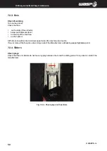
Page 50: ...top of the machine on the heaters All the fans should work at minimum speed when the machine is turned on If one or more of the fans are not working contact the Manufacturer addressing support 3dwasp...

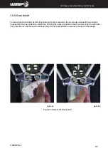
Page 51: ...ze shield To replace the Ooze shield deform it by allowing it to be removed by the six screws underneath the extruder To assemble the new protection widen it by hooking the holes provided on the six s...

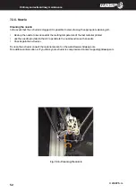
Page 52: ...Heat up the nozzle to be cleaned at the melting temperature of the last material printed use the needle provided in the kit to penetrate the nozzle and move the needle Check again the extrusion To cle...

Page 53: ...the removal of the filament as described in paragraph 5 3 First Start 4 Remove the Ooze shied protection as described in paragraph 7 2 5 Replacing Ooze shield protection 5 Unscrew and remove the nozzl...

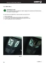
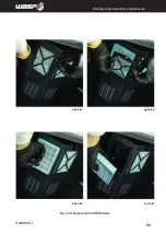
Page 54: ...osed of in accordance with the directives in force in your country and region The replacement of the HEPA filter is carried out with the machine turned off 1 Open the printer door 2 Unscrew the knob s...

Page 55: ...fig 7 2 8 c fig 7 2 8 d fig 7 2 8 e fig 7 2 8 f INTRODUCTION WASP S r l 55 Ordinary and extraordinary maintanance Fig 7 2 9 Replacement of HEPA filters...

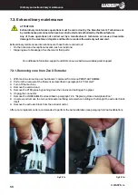
Page 56: ...ue to breakage of mechanical or fluid parts For additional information support and FAQs on our website www 3dwasp com support 7 3 1 Removing core from Zen X Extruder 1 WIth machine turned on use Autoh...

Page 57: ...fig 7 3 1 a fig 7 3 1 b fig 7 3 1 c fig 7 3 1 d INTRODUCTION WASP S r l 57 Ordinary and extraordinary maintanance Fig 7 3 1 Removing the Core from ZEN X Extruder...

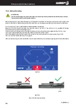
Page 58: ...d in ADVANCED TOOLS MANUAL LEVELING Based on the three point principle the machine moves the tool to the vertices of an equilateral triangle proportional to the aluminum bed fig 7 3 2 a At each point...

Page 59: ...INTRODUCTION WASP S r l 59 Ordinary and extraordinary maintanance fig 7 3 2 c fig 7 3 2 d fig 7 3 2 e fig 7 3 2 f Fig 7 3 2 Manual Leveling...

Page 60: ...INTRODUCTION WASP S r l 60 Ordinary and extraordinary maintanance...

Page 61: ...bed Right printing plate or glue based on the material to be printed Adequate speed flow and nozzle temperature in the first layer Adequate printing floor temperature basing on the material to be pri...

Page 62: ...ozzle on the bed so that they touch 5 Use the command PREPARE AUTOCALIBRATION 6 Notice AUTOCALIBRATION ENABLED message on the main window 8 2 2 Launch Autocalibration After the procedure for enabling...

Page 63: ...taken into consideration The nozzles must both be well calibrated Neither nozzle must be clogged The material must be correctly loaded on both nozzles The filament feed sensor must not be disabled in...

Page 64: ...the nonius used in the common caliber It consists of two overlapping grids with slightly different sized cells where each line corresponds to a tenth of a millimeter 0 1mm The position of the second e...

Page 65: ...4 5 5 4 3 2 1 0 1 2 3 4 5 T0 T0 T1 T1 5 4 3 2 1 0 1 2 3 4 5 5 4 3 2 1 0 1 2 3 4 5 INTRODUCTION WASP S r l 65 Use of the printer Fig 8 5b Example of non correct calibration grid Fig 8 5c Example of co...

Page 66: ...int The nozzle stopped during printing but the machine has continued to print The cases in which it is not possible to recover the print are when The printed part detached the printing floor The print...

Page 67: ...INTRODUCTION WASP S r l 67 Use of the printer Fig 8 6 Free Zeta System...

Page 68: ...h for your file s name and select it for printing 11 Once the printing has started the file is saved inside the machine s memory and the USB pendrive can be removed 8 7 2 Loading with Wi fi Access the...

Page 69: ...INTRODUCTION WASP S r l 69 Use of the printer Fig 8 7b Loading the gcode on printer server Fig 8 7a Loading gcode from USB pendrive...

Page 70: ...the movement in the specified direction Remember that whenever the machine touches an endstop the operation will be aborted EXTRUDING or RETRACTING E axis The procedure for moving X Y or Z axis is 1...

Page 71: ...INTRODUCTION WASP S r l 71 Use of the printer fig 8 6 Manual control command inside Prepare menu fig 8 6 Manual extrusion of the filament...

Page 72: ...y configure the printer In case a manual configuration is required FIXED IP it will be possible to do it through the WIFI configuration by selecting NOWIFI STATIC IP When the wifi settings are set the...

Page 73: ...Camera for remote monitoring of the print on the first layers Monitoring of the printer in Operational state Monitoring of the printing process in Printing state Gcode viewer with real time advancemen...

Page 74: ...the machine and the right value is essential for good operation This value is automatically saved by the machine during autocalibration After the AUTOHOME command it is possible in the main board to...

Page 75: ...INTRODUCTION WASP S r l 75 Use of the printer Fig 8 11a SET Z MAX window Fig 8 10 Resurrection system banner Fig 8 11b SET Z MAX procedure...

Page 76: ...o understand the 1 With the machine turned on check the cleanliness of the aluminum vacuum bed fig 8 12a The possible presence of debris can compromise the system s ability to reach the vacuum 2 Place...

Page 77: ...INTRODUCTION WASP S r l 77 Use of the printer Fig 8 12a Clean the aluminum vacuum bed Fig 8 12b Placing the silicone gasket Fig 8 12c Position the removable printing plate...

Page 78: ...TTENTION During operations the operator must wear all the necessary Personal Protective Equipment PPE 9 2 Disposal and dismantling Intheeventthattheprintershouldbetakenoutofserviceforaprolongedperiodw...

Page 79: ...destination concerning the disposal of waste so it is forbidden to disperse in the environment any type of processing residue oils etc subdividing the dismantled parts by type for a correct separate c...

Page 80: ...___ __________________________________________________________________________________ __________________________________________________________________________________ ______________________________...

Page 81: ...__________________________________________________________________________________ __________________________________________________________________________________ _________________________________...

Page 82: ...WASP S R L Via Castelletto 104 48024 Massa Lombarda RA Italia www 3dwasp com info 3dwasp com...

Reviews: