background image

   P

remises


© CSP S.r.l. 

1

8

1


General information 

1.3. Testing

The printer is tested directly by the Manufacturer during the phase of mounting and post mounting.

1.4. Warranty

The printers built by CSP S.r.l. are covered by a warranty for a period of 12 months for companies or VAT and 24 
months for individuals.
If during the period of validity, defective operations or faults of parts of the printer that fall within the cases 
indicated in the warranty occur, CSP S.r.l. (after the appropriate checks) will repair or replace the defective parts.
The defective parts under warranty are repaired or replaced free of charge by CSP S.r.l. .
The costs of transport and / or shipment are always charged to the Customer, as well as the return / return travel 
expenses related to the intervention of the Manufacturer’s technicians at the Customer’s premises.
The labor costs related to the intervention of the Manufacturer’s technicians at the Customer’s premises, for the 
removal of defects under warranty are the responsibility of the Manufacturer, except in cases where the nature 
of the defect is such that it can be easily removed on site by part of the Customer.
All consumables are excluded from the warranty, possibly supplied by the manufacturer together with the 
machines.

NOTE:

The guarantee lapses in the following cases:

•  In case of default or other contractual non-fulfillment;

•  Improper use of the printer

•  Failure to comply with the standards and maintenance intervals

•  Tampering

•  The printer is returned to the Manufacturer in a different packaging from the one supplied at the 

time of purchase;

•  Use of non-original spare parts, ie not supplied directly by the Manufacturer;

•  Extraordinary interventions not carried out by personnel not sent by the Manufacturer;

•  Any variation and / or non-observance of what is indicated in the technical documents and in 

this manual entails the forfeiture of the technical and functional guarantees, and release the 

Manufacturer of the printer from any responsibility.

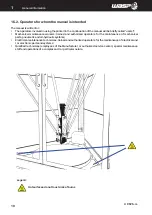
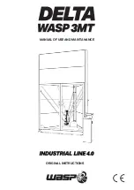
1.2.1. Position of the label on the printer

Summary of Contents for Delta WASP 3MT INDUSTRIAL 4.0 LDM

Page 1: ...MANUAL OF USE AND MAINTANANCE ORIGINAL INSTRUCTIONS ...

Page 2: ... the best results from DELTA WASP 4070 INDUSTRIAL 4 0 No part of this publication may be reproduced stored in a filing system or transmitted to third parties in any form or by any means without the Manufacturer having issued a prior written authorization The Manufacturer reserves the right to make changes to its products at any time and without notice in order to constantly increase the quality th...

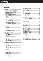
Page 3: ...board 27 5 2 2 Menù print 28 5 2 3 PREPARE menu 29 5 2 4 ADVANCED menu 30 5 2 5 WIFI settings 31 5 2 6 GCODE 32 5 2 7 INFO menu 33 5 3 First start 6 First use of the printer 34 6 1 General warnings 34 6 2 Gcode creation 35 6 3 Slicing software 35 6 4 Autocalibration 35 6 5 Loading removal of the filament 35 6 5 1 Loading pellet 35 6 5 2 Loading filament 36 6 6 Adhesion to the bed 36 6 7 Selecting ...

Page 4: ......

Page 5: ...cupient on the printer itself or in its immediate vicinity In the second case the location of the manula must me indicated on the printer clearly It is susceptible of updates which appropriately classified will be transmitted to the employer in order to update the consultation copy s The recipient must ensure that the personnel authorized by him to start up use maintain and transport the printer h...

Page 6: ...is mandatory to keep this manual and all attached documents in an easily accessible place near the printer and known to all users operators and maintenance personnel Operators and maintenance technicians must be able to quickly find and consult the manual in any situation The manual is an integral part of the printer for security purposes Therefore It must be kept intact in all its parts It must f...

Page 7: ...Zaganelli 26 48024 Massa Lombarda RA Italy Tel 39 0545 82966 info 3dwasp com www 3dwasp com 1 2 Indentification label The printer is CE marked and complies with all relevant provisions Machinery Directive 2006 42 EC EMC Directive 2014 30 EU and LVD Directive 2014 35 EU EN 55022 EN 55024 EN 60204 1 ThemarkingcanbeidentifiedbymeansofanidentificationplateoftheManufacturerasrequiredbytheMachinery Dire...

Page 8: ...e Customer s premises for the removal of defects under warranty are the responsibility of the Manufacturer except in cases where the nature of the defect is such that it can be easily removed on site by part of the Customer All consumables are excluded from the warranty possibly supplied by the manufacturer together with the machines NOTE The guarantee lapses in the following cases In case of defa...

Page 9: ...what we described in the documentation presented Possible operations on the printer can Mechanics Electrical MECHANICAL NATURE INTERVENTIONS Any intervention of a mechanical nature must be carried out in strict compliance with the directives required by currentsafetyregulations Itisabsolutelyforbiddentoperformanytypeofmechanicalmaintenanceintervention on the printer during the operating cycle or i...

Page 10: ...rs trained and authorized operators for the maintenance of mechanical parts pneumatic and oil hydraulic systems Electrician maintenance technicians trained and authorized operators for the maintenance of electrical and or electronic parts and systems Qualified technicians employees of the Manufacturer or authorized service center special maintenance staff and operations of a complex and or particu...

Page 11: ...ER WHEN MACHINE IS WORKING Premises CSP S r l 1 11 1 General information Legend Hot surface do not touch risk of burns WARNING DO NOT ENTER WHEN MACHINE IS WORKING Attenzione piano caldo non toccare rischio di scottatura READ CAREFULLY THE USER MANUAL BEFORE OPERATING ON THE MACHINE ...

Page 12: ...Premises CSP S r l 1 12 1 General information Legend Hot surfaces do not touch risk of burns ...

Page 13: ...compromiseitsright behaviour The Door sensor activates anytime the door is open and automatically pauses any action on the machine including heating movements and tool change OVERHEATING BLOCK The machine is designed with a control system to prevent the overheating of its parts by blocking the heating parts as the temperatures recorded overcome the saftey thresholds set by the Manufacturer 1 5 4 R...

Page 14: ...and therefore be aware of the tasks entrusted to him who has responsibility for the job Below is a description of the professional profiles for the operators involved in the printer User Qualified personnel able to perform simple tasks trained on using the printer It supervises the proper functioning of the same and the eventual first intervention in case an alarm condition occurs Mechanical maint...

Page 15: ...uations or operations in which there is the possibility of causing damage to the environment NOTE Indicate the notes warnings suggestions and other points on which you want to draw the reader s attention or complete the explanation with further information Personal protective equipment PPE The graphic symbols used in this manual are indicated below to indicate the need to wear certain PPE PROTECTI...

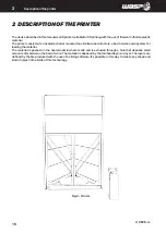
Page 16: ...t structure a bed of work and a system for loading the material The material is pushed on the heated nozzle where melts and is extruded through a hole that deposes small amounts of material on the bed of work The material is deposed by the toolhead layer on layer The layers are defined by the file produced with the use of a slicing software It s possible in this way to create any shape and kind of...

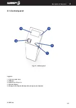
Page 17: ...r l 2 17 Description of the printer 2 Fig 2 1 Control panel 2 1 Control panel Legend 1 Ethernet cable door 2 USB door 3 Switch turn off turn on 4 Operator display 5 Display control handle Rotates left and right and is clickable ...

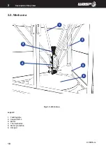
Page 18: ...1 3 4 5 6 2 Premises CSP S r l 2 18 Description of the printer 2 Fig 2 2 Work area 2 2 Work area Legend 1 Feeding pipe 2 Support arms 3 Motor 4 Thermal barrier 5 Motor protection 6 Hot pad ...

Page 19: ...1 3 2 Premises CSP S r l 2 19 Description of the printer 2 Fig 2 3 External area of the printer 2 3 External area of the printer Legend 1 Material ingress 2 Material Tank 3 Supply ...

Page 20: ...nd cover Metal sheet and aluminium Print bed Rectified aluminium Movement Rolling on anodized aluminum slide Motors Stepper Nema 34 Electrical features Input 220 240 V 50 60 Hz Absorbed power Pellet extruder 660W max Spitfire extruder 60 W Hot pad 1600 W max Heater 3000 W Use features Environment of use 20 30 C Warehouse 0 30 C Nozzle max 275 C Heated bed max 110 C 3D printing informations Technol...

Page 21: ...scribed in paragraph 2 6 Failure to comply with safety standards Operation of the printer with procedures other than those described in this manual Use components not foreseen in the design phase Failure to comply with established maintenance schedules Carry out operations on the printer that involve the modification of components or parameters that affect the work cycle Alter the calibration of t...

Page 22: ... Equipment PPE 3 1 1 Delivery of the printer Normally the printer is shipped disassembled in two wooden cases The printer is carefully checked before delivery to the shipper Upon receipt make sure that The printer has not been damaged in transit Any packaging has not been tampered with resulting removal of parts from the inside The supply corresponds to the order specifications NOTE If the printer...

Page 23: ...p it steady on one side 3 3 Content The printer is supplied with Booklet of introduction to the use of the printer USB pendrive glues 3 4 Lifting and handling of the printer ATTENTION Theweightoftheprinterisshowninparagraph2 4 Technicaldata Itisthereforenecessarytouse the lifting equipment whose expected flow is adequate for the weight to be lifted ATTENTION As long as the printer is not completel...

Page 24: ...cessary to prepare the necessary operating space by referring to the dimensions expressed in mm shown in paragraph 2 4 Technical data The room must also be Equipped with the adequate power supply line Installed in environments with brightness equivalent to that expected for industrial environments as indicated by the regulations in force in the country of destination regarding safety in the workpl...

Page 25: ...hnical data Before connecting the printer s power cord to the electrical outlet check that the system s power consumption and voltages are suitable 4 3 Air connection Before putting the material loading system under pressure check that all parts are assembled correctly and that the system pressures are suitable ATTENTION The operations relating to these activities must be carried out by authorized...

Page 26: ...raph 1 5 General safety warnings Furthermore the specific requirements for safe interaction with the printer related to this chapter are detailed in the following paragraphs ATTENTION The operations related to these activities must be performed by authorized and professionally qualified personnel ATTENTION During operations the operator must wear all the necessary Personal Protective Equipment PPE...

Page 27: ...aunching the print It is intended to be the principal tool for the monitoring and control of the printer Legend 1 Extruder temperature clicking it can be modified 2 Wifi informations 3 Operative information position feed flow state autocalibration on off 4 Bed temperature by clicking it can be modified 5 Toolbar 6 Door open closed Fig 5 2 1 Main board ...

Page 28: ...e print Legend 1 Auto home puts the machine in position of zeroing of the axes 2 Unload material heats extruder and removes material inside 3 Load material heats extruder and loads material inside 4 Autocalibration heats extruder and performs autocalibration par 8 3 5 Gcode gives access to gcodes list to proceed with the printing par 8 4 Fig 5 2 2 Menu PRINT ...

Page 29: ...tains useful tools to be used sometimes Legend Free Zeta system enters in Free Zeta System par 8 7 Set Z max allows to set a new height for the machine par 8 8 Manual extrusion enters in Manual Extrusion Manual leveling enters in Manual Leveling board Disable motors disable stepper motors Fig 5 2 3 Menu PREPARE ...

Page 30: ...aordinarely Legend Send arbitrary command contains a keyboard for launching commands directly to the board Wifi settings for connecting the machine to the wifi nerwork par 8 13 Reload UI reloads the graphic interface Camera shows what the camera is seeing and can read QR codes Settings Allows to set different advanced settings Fig 5 2 4 Menu ADVANCED ...

Page 31: ...he machine to wifi network par 8 13 Legend 1 SSID to chose the desidered network between all visible ones 2 PWD Allows to insert a password if present 3 AUTH makes you specify what kind of connection you re working with 4 USER Allows to insert use if present Clicking UPDATE the machine restarts with new settings Fig 5 2 5 WIFI settings ...

Page 32: ...NT menu by chosing GCODE you can launch gcodes and moving them from the USB to the printer par 8 5 Legend 1 Chose USB Drive Printer Drive 2 Gcode list the ones on the drive present and icon beside the name 3 Arrows for the navigation 4 GO launchs selected print Fig 5 2 6 GCODE ...

Page 33: ...printer 5 5 2 7 INFO menu INFO contains useful video tutorials for basic and advanced operations you can access anytime you want and as you exit videos are paused Also if you access from specific pages it already directs you to the relative video ...

Page 34: ...raphs ATTENTION The operations related to these activities must be performed by authorized and professionally qualified personnel ATTENTION Pay particular attention during the various stages of the procedures it is essential to wear gloves because there is a risk of burns ATTENTION During operations the operator must wear all the necessary Personal Protective Equipment PPE NOTE Inside the USB pend...

Page 35: ... the straps To carry out the calibration see chap 8 3 Autocalibration following the whole procedure carefully Before starting the automatic calibration it is advisable to set the desired table temperature according to the material and wait at least 15 minutes for the temperature on the table to be evenly distributed Make sure that the print bed is clean and the aluminum of the bed clearly visible ...

Page 36: ...on the spool support Insert the thread inside the end of thread sensor and slide it until it reaches the hole of the thread take up Confirm on the display and wait for the extrusion process to end 6 6 Adhesion to the bed Before each print it is necessary to put a layer of glue supplied with the printer on the aluminum bed 6 7 Selecting gcode Select the printing file from PRINT GCODE Printing will ...

Page 37: ...Premises CSP S r l 6 37 First use of the printer 6 6 9 Piece removal Remove the piece from the bed by using a spatula For information and support please visit F A Q section on our website www 3dwasp com ...

Page 38: ... requirements for safe interaction with the printer related to this chapter are detailed in the following paragraphs ATTENTION The operations related to these activities must be performed by authorized and professionally qualified personnel ATTENTION Payparticularattentionduringthevariousstagesoftheprocedures itisessentialtoweargauntlets because there is a risk of burns ATTENTION During operations...

Page 39: ...1 Belts Check tension 160 hours Ball joints Lubrication 160 hours Par 7 2 2 Extruder fans Check if works 160 hours Par 7 2 3 Sliders Check plays 160 hours Par 7 2 4 Hot pad Cleaning If too dirty Par 7 2 5 Loading system Check if works 160 hours 7 2 1 Fan filter Verify and replace filter In the control unit there are three fans with filter one on the right side one on the left side and one in the r...

Page 40: ...ng The hot pad is cleaned with the machine off It is necessary in the cases of Impaired flatness Dirty that prevents adhesion during printing Aesthetic reasons To carry out the operation it is necessary to remove the top by removing the three fixing elements Once removed clean with water and detergents as needed The use of sharp parts that can damage the surface and abrasive machines that can comp...

Page 41: ... by the Manufacturer Any of these operations not carried out by a manufacturer s technician can cause irreversible damage to the machine or its parts and therefore renders the warranty null and void Extraordinary maintenance interventions are those that are carried out On the occasion of exceptional events such as revisions Stopping due to breakage of mechanical or fluid parts Per info e assistenz...

Page 42: ...ivided into two main procedures nozzle cleaning screw cleaning CLEANING THE NOZZLE The cleaning of the nozzle is used to remove any small parts or debris that have become blocked in the final part of the extruder and obstruct the correct exit of the material To clean the nozzle follow the procedure below 1 Launch the Autohome command in the PRINT menu 2 Heat the extruder to a temperature of 180 C ...

Page 43: ...fig 7 4 1 a fig 7 4 1 b fig 7 4 1 c fig 7 4 1 d Premises CSP S r l 43 Ordinary and extraordinary maintanance 7 ...

Page 44: ...s parts If not carried out correctly the procedure can also significantly damage the extruder and involve risk for the operator To clean the screw follow the procedure below 1 Heat the extruder to 190 C fig 7 4 2 a 2 Using the Move axis command bring the extruder to working height 3 Check that the cables on the side are free from elastic bands and cable ties fig 7 4 2 b 4 With extreme care release...

Page 45: ...fig 7 4 2 a fig 7 4 2 c fig 7 4 2 d fig 7 4 2 b Premises CSP S r l 45 Ordinary and extraordinary maintanance fig 7 4 2 Cleaning the screw 7 ...

Page 46: ...e front bezel on the extruder fig 7 4 2 g 8 With an aspirator remove the granules in the upper part of the extruder fig 7 4 2 h 9 Unscrew the two cylindrical head screws above the extruder with a 4 mm Allen key fig 7 4 2 i 10 Remove by pulling the motor upwards with the screw Pay attention to the molten material during extraction fig 7 4 2 j 7 ...

Page 47: ...fig 7 4 2 g fig 7 4 2 i fig 7 4 2 j fig 7 4 2 h Premises CSP S r l 47 Ordinary and extraordinary maintanance fig 7 4 2 Cleaning the screw 7 ...

Page 48: ... 11 With pliers remove the still hot material from the screw fig 7 4 2 k 2 12 If necessary heat the plastic on the screw with a gun fig 7 4 2 l 3 13 Clean any residues with an iron brush fig 7 4 2 m 4 14 Reassemble everything with the reverse process fig 7 4 2 n 7 ...

Page 49: ...fig 7 4 2 k fig 7 4 2 m fig 7 4 2 n fig 7 4 2 l Premises CSP S r l 49 Ordinary and extraordinary maintanance fig 7 4 2 Cleaning of the screw 7 ...

Page 50: ... to exclude the hypothesis that this is due to other factors for example 1 Incorrect print code gcode 2 Extrusion temperature not suitable for the material 3 Unsuitable material In the event of a clogged Spitfire extruder it is possible to dismantle only the Spitfire module the red part and clean it according to the instructions available on the Manufacturer s website Alternatively the Spitfire mo...

Page 51: ...Premises CSP S r l 51 Ordinary and extraordinary maintanance 7 ...

Page 52: ... check that The extruder does not print too close to the surface preventing extrusion during printing The extruder temperature is actually that necessary for the material used It is recommended to check that the first printed layer adheres well to the plate 8 3 Autocalibration Autocalibration is a command that performs an automatic calibration of the height and leveling parameters The autocalibrat...

Page 53: ...fig 8 3 a fig 8 3 b fig 8 3 c fig 8 3 d Premises CSP S r l 53 Use of the printer fig 8 2 Autocalibration 8 ...

Page 54: ...Premises CSP S r l 8 54 Use of the printer 8 Fig 8 3a Explaining of calibration grid fig 8 4 GCODE menu ...

Page 55: ...can be removed Loading with Wi fi 1 Access printer control from your browser write the IP address shown on the machine in the URL of your browser see chapter 8 14 2 Enter the Control page and click on Upload gcode blue button 3 Wait for the gcode to load 4 At the end the file can be selected for printing If the internal memory of the printer is full it will not be possible to add other gcodes And ...

Page 56: ...power supply and the compressed air inlet are correctly connected fig 8 6 1 a 1 To load the tank first check that the drain flap is properly closed fig 8 6 1 b 2 Open the upper door and fix it with the magnet to the wall of the machine 3 Carefully pour the material into the tank as far as desired fig 8 6 1 c 4 Close the door 5 Turn on the compressor if it is off 6 Adjust the pressure with the cont...

Page 57: ...fig 8 6 1 b fig 8 6 1 c fig 8 6 1 e fig 8 6 1 d Premises CSP S r l 8 57 Use of the printer 8 fig 8 6 1 Loading the material Pellet extruder ...

Page 58: ...e spool fig 8 6 2 a Reposition the horizontal element on the spool support fig 8 6 2 b Drag the filament inside the end of thread sensor on top of the extruder fig 8 6 2 c Accompany the filament at the entrance of the thread take up Set the nozzle temperature to that of the material to be printed Turn the control knob counterclockwise until the material is correctly extruded fig 8 6 2 d Before lau...

Page 59: ...fig 8 6 2 a fig 8 6 2 b fig 8 6 2 d fig 8 6 2 c Premises CSP S r l 8 59 Use of the printer 8 fig 8 6 2 Loading the material Spitfire extruder ...

Page 60: ...overed and start printing 7 Close the door of the machine 8 8 Modifiy height The height ofthemachineindicatesthedistancesavedbythemachinebetweenthetipofthenozzleandthe bed It is a fundamental value for the correct operation of the machine During the self calibration procedure the height of the machine is automatically saved It is however possible to save the manual height for example if the condit...

Page 61: ...fig 8 8 a fig 8 8 b fig 8 8 c Premises CSP S r l 8 61 Use of the printer 8 Fig 8 8 Modify the height ...

Page 62: ...rryingoutthecalibrations so that thermal deformations are already considered 1 Turn on the machine and bring it to zero with the Autohome command fig 8 9 a 2 Make sure you have removed any printed parts from the build plate 3 Enter the Manual leveling command inside the PREPARE menu fig 8 9 b 4 The interface will allow the user to move to the three plan control positions 5 At each external point o...

Page 63: ...fig 8 9 a fig 8 9 b fig 8 9 c fig 8 9 d Premises CSP S r l 8 63 Use of the printer 8 Fig 8 9 Manual leveling ...

Page 64: ...2 Disconnect all the connectors that connect the extruder to the machine to Self calibration sensor fig 8 10 a b Thermocouple sensor fig 8 10 b c General connector fig 8 10 c d Pellet feed sensor ATTENTION The extruder change must be carried out with the machine off and making sure that the various parts are not at temperature ATTENTION The operation must be carried out by at least two professiona...

Page 65: ...fig 8 10 a fig 8 10 b fig 8 10 c fig 8 10 d Premises CSP S r l 8 65 Use of the printer 8 Fig 8 5 2 Gcode wifi loaded with Octoprint ...

Page 66: ...es on the side of the machine so that they do not get in the way fig 8 10 e 4 Loosen the two front screws on the top of the extruder with a 3mm Allen key fig 8 10 f 5 Remove the pellet feeding pipes fig 8 10 g h 6 With an aspirator remove the granules in the upper part of the extruder fig 8 10 m n ...

Page 67: ...fig 8 10 g fig 8 10 h fig 8 10 m fig 8 10 n Premises CSP S r l 8 67 Use of the printer 8 Fig 8 5 2 Gcode wifi loaded with Octoprint ...

Page 68: ...second extruder to be assembled 9 With extreme care unhook the carabiner from the pellet extruder and re attach it to the Spitfire extruder fig 8 10 q 10 Reverse operation 7 for attachment to the arms 11 Correctly reconnect the cables needed for the extruder to Self calibration sensor b Thermocouple sensor c General connector NB Pellet feed sensor not present in the Spitfire extruder 12 Carry out ...

Page 69: ...fig 8 10 o fig 8 10 p fig 8 10 q Premises CSP S r l 8 69 Use of the printer 8 ...

Page 70: ...that in the period of time between turning off the machine and launching the Resurrection command it involves cooling the molded piece which in some cases can cause problems in recovering the print 8 12 Removal of the print To perform a good removal of the piece from the printing plate it is required That the extruder is in the autohome position That the printer is stopped whether on or off is not...

Page 71: ...fig 8 12 a fig 8 12 b Premises CSP S r l 8 71 Use of the printer 8 ...

Page 72: ... to the same wifi network as the printer To enter the Octoprint control environment 1 Make sure that both the computer and the printer are connected to the same wifi network 2 Enter the IP address that appears on the machine in the URL of the browser eg http 192 128 12 114 3 The browser will enter the Octoprint platform for monitoring and controlling the machine 4 To access all the functions log i...

Page 73: ...Premises CSP S r l 8 73 Use of the printer 8 ...

Page 74: ...moving the printing material with the pellet extruder is an operation that consists of two phases Empty the extruder with an aspirator as shown in par 7 4 2 Cleaning the screw fig 7 4 2 g h Empty the tank as indicated below in this paragraph To empty the tank correctly proceed as follows 1 Place a container under the tank making sure that it can collect the granule well 2 Open the drain flap by li...

Page 75: ...fig 8 14 1 a fig 8 14 1 b fig 8 14 1 c Premises CSP S r l 8 75 Use of the printer 8 fig 8 14 1 Emptying material Pellet ...

Page 76: ... consists of two phases 1 Removethefilamentfromtheextruder runthe UnloadFilament commandinthe PRINT menu fig8 14 2a 2 Manually remove the filament from the extruder 3 Remove the spool from its support remove the horizontal element from the support and then remove the spool Then reposition the horizontal element on the support fig 8 14 2 b ...

Page 77: ...fig 8 14 2 a fig 8 14 2 b Premises CSP S r l 8 77 Use of the printer 8 fig 8 14 1 Emptying material Spitfire ...

Page 78: ...A ON OFF button used to switch the room heating system on and off B SET button used to set the temperature to be reached C UP button to increase the figure on the display D DOWN button used to reduce the figure on the display When no action is taken on the controls and the heating is on the display will indicate the temperature in the chamber at the time of reading fig 8 15 c To set a temperature ...

Page 79: ...fig 8 15 a fig 8 15 b Work Set C 19 2 Work Set C 40 0 fig 8 15 c fig 8 15 d Premises CSP S r l 8 79 Use of the printer 8 fig 8 15 Heaters and chamber temperature control ...

Page 80: ...ions it is necessary to create around the printer a sufficiently large and orderly space in order to allow all the necessary movements without risk created by the surrounding environment ATTENTION Observe the requirements imposed by the laws in force and by the authorities in charge of the country in which the demolition takes place If the mechanical parts need to be dismantled it must be remember...

Page 81: ...2 19 EU on waste electrical and electronic equipment WEEE ATTENTION The user has the obligation to dispose of the equipment at consortia and collection centers for the treatment and recovery of WEEE 9 3 Instructions for emergency situations ATTENTION In the event of a fire the operator must immediately give the alarm and move away from the area to allow the intervention of trained personnel equipp...

Page 82: ...____ __________________________________________________________________________________ __________________________________________________________________________________ __________________________________________________________________________________ __________________________________________________________________________________ _______________________________________________________________...

Page 83: ..._ __________________________________________________________________________________ __________________________________________________________________________________ __________________________________________________________________________________ __________________________________________________________________________________ __________________________________________________________________...

Page 84: ...CSP S R L Viale Zaganelli 26 48024 Massa Lombarda RA Italia Tel 39 0545 82966 www 3dwasp com info 3dwasp com Fig 8 13 Change the extruder Multi core ...

Page 85: ...Premises CSP S r l 8 85 8 Fig 8 13 Change the extruder Multi core ...
Reviews: