
Doc. P/N: WSP-009-005
Version: V1.5
Issue Date: October 2013
www.wassp.com
Page 19 of 73
Installation Manual
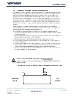
6.2 BTxR Installation
6.2.1 BTxR Installation Considerations
For maintenance purposes, the PCB assembly can be removed from the case in situ. Always
leave at least 600 mm clearance at the faceplate end cover to allow the PCB assembly to be
withdrawn from the case.
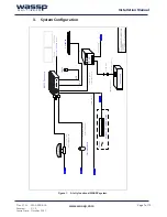
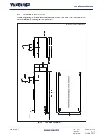
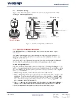
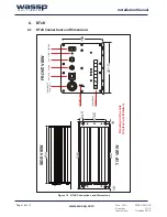
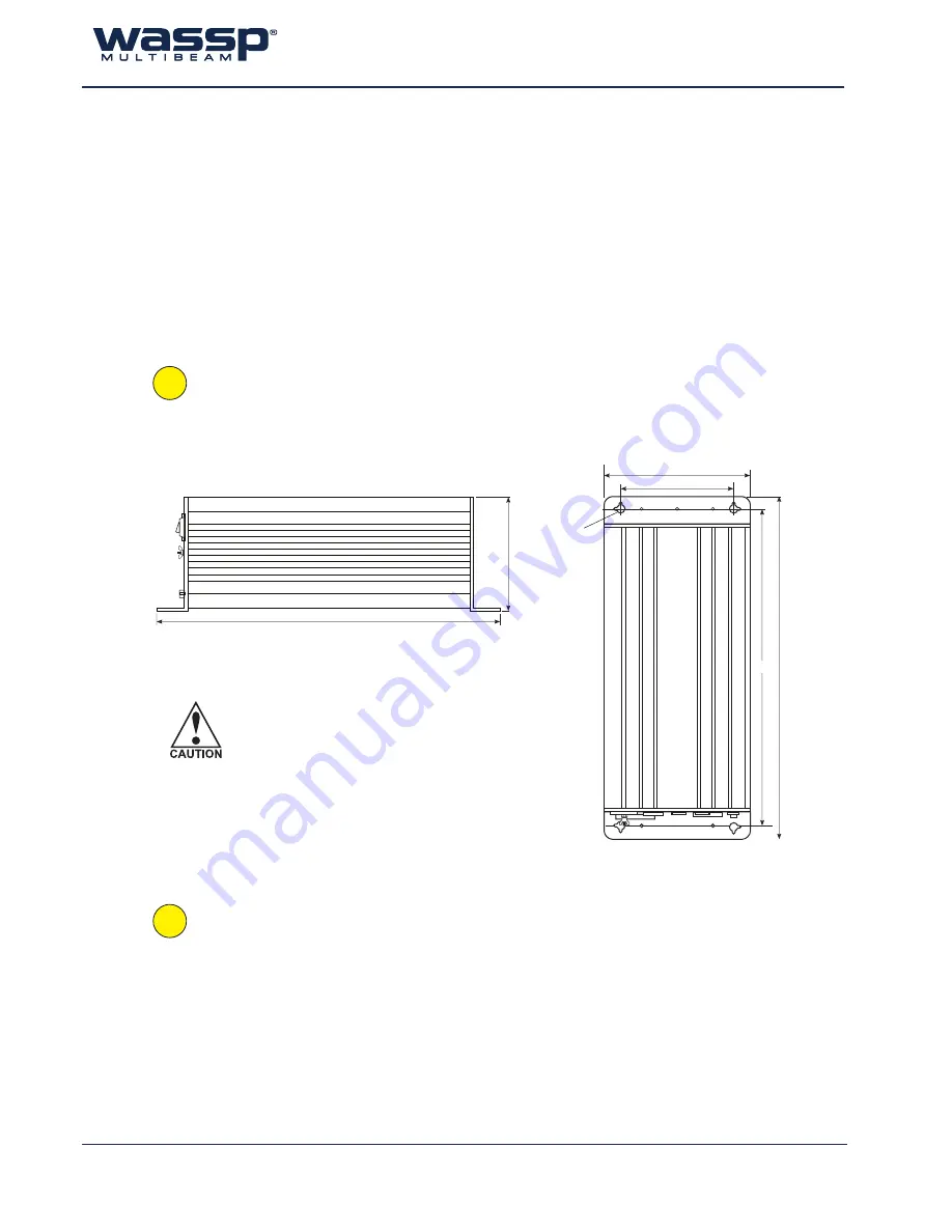
6.2.2 BTxR Installation
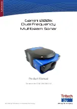
Using the mounting flanges on the end covers, the BTxR can be mounted vertically on a
bulkhead, or horizontally on the floor. See “Figure 10. BTxR Connections and Dimensions” on
page 18 and “Figure 11. BTxR Mounting Diagram” on page 19 for BTxR dimensions and mounting
clearances.
Using the mounting holes on the mounting flanges, secure the BTxR to the mounting
surface.
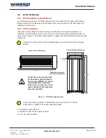
80
Vertical Bulkhead Mounting
Horizontal Floor Mounting
Drawing not to scale
All sizes in millimeters
535
535
497
Mounting
holes
172
221.5
456
Figure 11. BTxR Mounting Diagram
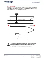
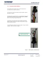
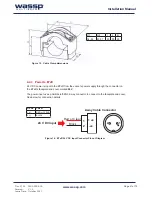
The BTxR can be mounted with
the transducer cable feeding in
from the top. WASSP Ltd. do not
recommend this as any water
leaks could run down any of the
cables attached to the faceplate
and enter the BTxR.
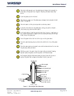
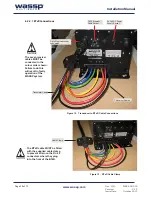
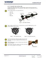
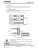
Connect the following cables to the faceplate end cover. See “6.2.2.1 BTxR
Connections” on page 20
f
or cable connection details:
►
Transducer cable to BTxR.
►
WASSP Processor CAT5 cable to BTxR
►
24 V DC power to BTxR
1
2