Doc. P/N: WSP-009-005
Version: V1.5
Issue Date: October 2013
www.wassp.com
Page 45 of 73
Installation Manual
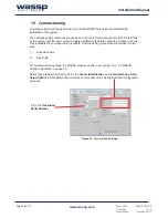
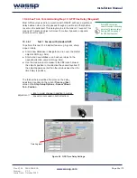
10.1.5 Commissioning Step 5: Electrical Noise
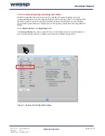
Open a
Sonar
display as a full screen display. See section “5.1 Sonar View” on page
33 of the Operator Manual.
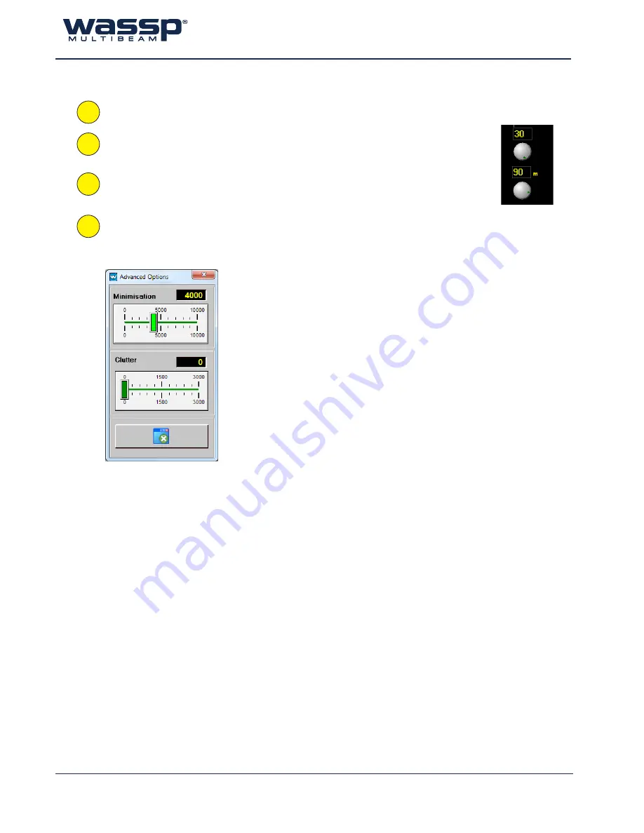
On the
Menu Task Bar
, set the
Range Knob
to manual (double click switches between
auto and manual, manual being yellow) and change the range dial to 90 m. Double click
on the Sonar display to ensure all 90 metres are displayed.
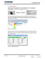
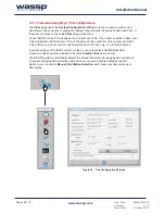
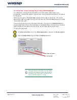
On the
Menu Task Bar
, set the
Gain Control Knob
to 30.
Double click on the
Gain Control Knob
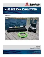
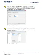
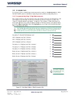
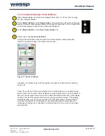
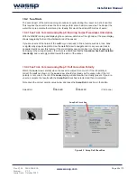
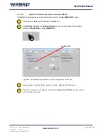
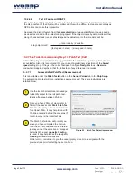
To adjust the minimisation and the clutter for a clearer display, access Advanced
Options, by double clicking on the Gain Control button.
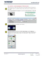
If possible, do this test at rest with the engine out of gear and with all other sounding
devices off.
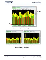
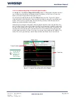
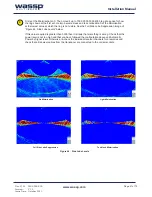
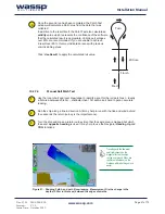
Check the centre line of the Sonar display for a consistent signal or a consistent pulse
down a radial line. If present, this is evidence of noise signals common to all channels. If
this noise can be clearly seen as more than a faint blue-white vertical line on the display,
it is likely that all of the receiver channels are picking up electrical noise. If the display
is relatively clean, move on to the next test. The most likely cause of noise problems
is incorrect termination of the transducer cable grounding and screening. Ensure a
low gauge grounding wire is attached to a solid ground which is common to the power
supply ground.
1
2
3
4
Figure 39. Advanced Options