


Doc. P/N: WSP-009-005
Version: V1.5
Issue Date: October 2013
www.wassp.com
Page 59 of 73
Installation Manual
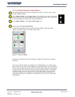
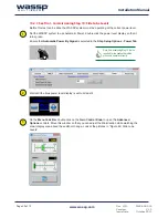
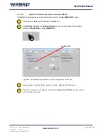
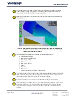
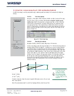
Figure 53. Pitch Corrections
w
d/2
α
d
tan(
α
) = -d/(2w)
α
= tan-1 (-d/2)
If object moves as above the sign is negated otherwise remove the -ve sign
from this equation.
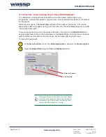
Enter the calculated value for
α
into the Heading Offset on the Sensor Tab.
Re-running the same test
with the offset modified
is another way to check
the sign has been entered
correctly. The object will not
move if everything is correctly
configured.
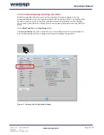
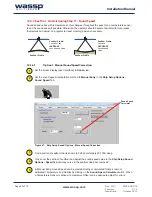
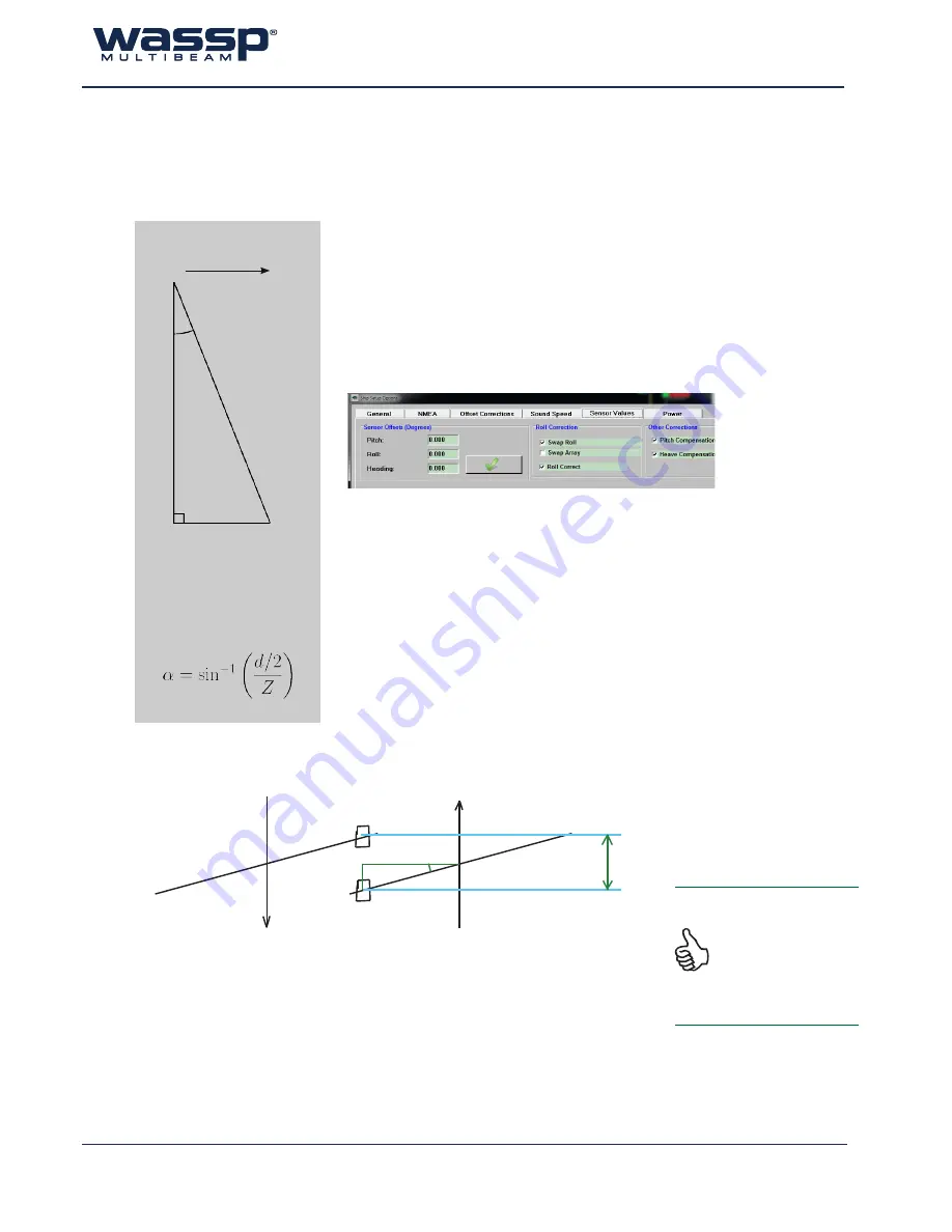
10.2.8 Sea Trial - Commissioning Step 15 : Pitch and Heading (Optional)
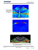
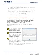
If GPS Time delay could be completed using variable speed then attempt to compute pitch offset as
follows:
d = distance object moves
Z = depth
α = pitch offset
(-ve pitch offset if object
moves ahead of vessel)
Vessel Direction
d/2
α
Z
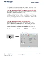
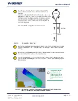
10.2.8.1
Pitch Correction
Requires: >10m depth, Distinct Object, DGPS or better, Accurate Time Lag.
Once the Time Lag is accurately ascertained
using the variable speed
method
described in the previous commissioning step, a Pitch Correction
value can be ascertained by having the Ship travel over a distinct object
in opposite directions. The object will move if the Pitch offset is incorrect
and use of trigonometry will determine the Pitch offset between the Motion
Sensor and the Transducer. Enter this number into the Pitch Offset on the
Sensor Values Tab.
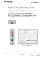
10.2.8.2
Heading Correction
Requires: DGPS or better, Distinct Object and >10m depth.
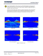
A note on heading correction was included in “10.1.6 Commissioning Step 6:
Heading (Yaw) Offset” on page 47. To determine a more accurate heading
correction between the heading sensor and the transducer orientation we
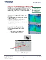
need high accuracy position sensors and corrected seafloor data. Approach
a small distinct seafloor feature so that the port side of the swath covers the
object. Next pass over the object so that the starboard side of the swath
crosses the same object in the opposite direction. It is important that these
two tracks are on exactly parallel heading lines. Use basic trigonometry
to calculate the required heading offset that will allow the object to remain
stationary. Redo the heading test to check that the heading offset was
entered correctly.