background image

Doc. P/N: 

WSP-009-004 

Version: 

V1.3

Issue Date:  August 2013

www.wassp.com

Page 15 of 62

Operator Manual

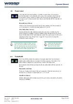
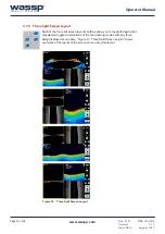
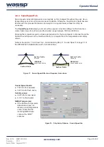
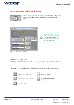
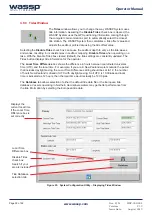
The transmit power level selector / indicator controls how much power is 
put into the water i.e. the strength of the ping. It can operate in both manual 
or automatic modes. However, initially use auto power by signal (BLUE) or 
~Power Level 7 in the manual mode until you are familiar with the operation of 
the unit.

Manual Mode (Yellow)

There are 14 transmit power levels that can be selected. Click the increment 

RUGHFUHPHQW±EXWWRQVWRDGMXVWEHWZHHQDQG

Auto Mode (Blue / Green)

Double-clicking the LED indicator selects the auto mode, indicated by the 
LEDs changing to GREEN


or BLUE. GREEN automatically selects the power 

based on the depth. BLUE automatically selects the power based on the return 
signal level. See “4.8.6 Power Tab” on page 25 if you wish to change the 
Automatic Power settings.
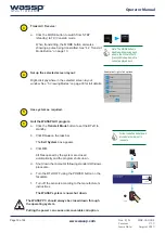
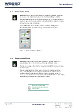
4.5 

Power Level

Double-click on the transmit power 
level window to switch between 
manual and automatic modes.

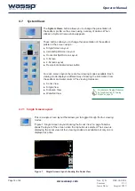
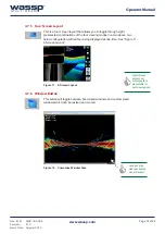
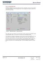
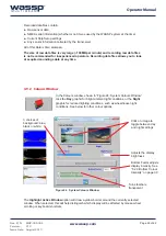
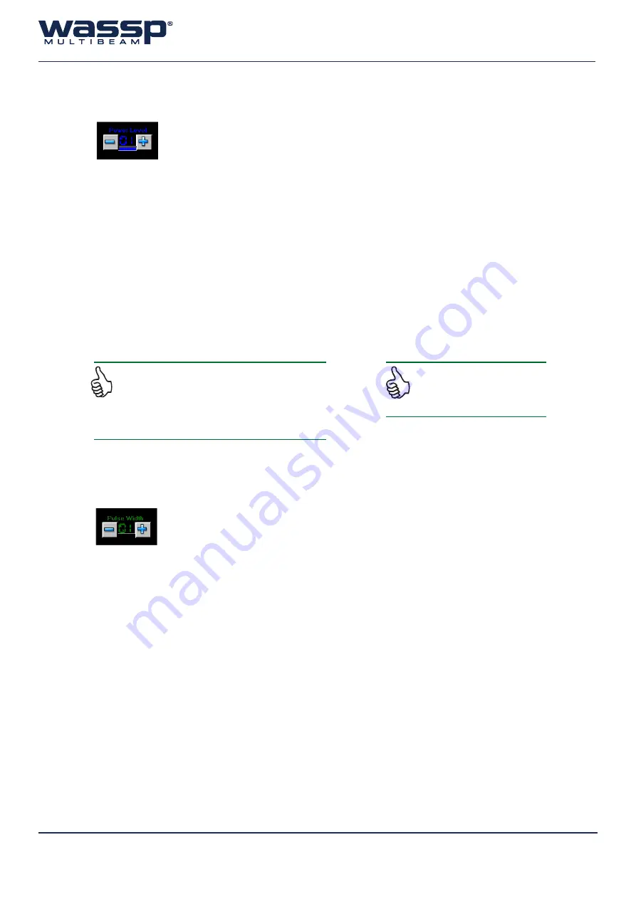
7KH3XOVH:LGWKDGMXVWVWKHGXUDWLRQRIDVLQJOHSXOVHIURPWKHWUDQVGXFHU

Higher pulse widths allow more power but at the expense of resolution. The 
Pulse Width is displayed as preset times in tenths of milliseconds.

6HWWRDGMXVWDXWRPDWLFDOO\E\XVLQJ$XWR0RGHXQWLOIDPLOLDUZLWKWKHRSHUDWLRQRI

the unit.

Manual Mode (Yellow)

There are 5 pulse width levels that can be selected. Click the increment (+) or 

GHFUHPHQW±EXWWRQVWRDGMXVWEHWZHHQ

Auto Mode (Green)

Double-clicking the LED indicator selects the auto mode, indicated by the LEDs 
changing to GREEN.

4.6 

Pulse Width

To allow Auto Mode to change from Power Level 8 to 

3RZHU/HYHOWKH3XOVH:LGWKPXVWEHVHWWRDWOHDVW

0.2ms (02), otherwise the power level will not increment. 
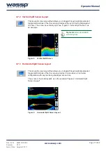
Ensure that the pulse width is set to Auto Mode to avoid 

ZHDNVHDÀRRUUHWXUQVLQGHHSHUZDWHUVHHEHORZ

Summary of Contents for WMB-3250

Page 1: ...Doc P N WSP 009 005 Version V1 1 Issue Date June 2012 OPERATOR MANUAL WMB 3250 Doc P N WSP 009 004 Version V1 3 Issue Date August 2013...

Page 2: ...ion Electrical Safety Fire electrical shock or equipment damage may occur if the transceiver becomes wet The equipment is rated for operation at BTxR 24 V DC WASSP PC 9 36 V DC Check the PC power supp...

Page 3: ...16 4 7 1 Single Screen Layout 16 4 7 2 Vertical Split Screen Layout 17 4 7 3 Horizontal Split Screen Layout 17 4 7 4 Three Split Screen Layout 18 4 7 5 Four Screen Layout 19 4 7 6 Window Button 19 4 8...

Page 4: ...tly Asked Questions FAQs 7 1 The System is transmitting too slowly how can I speed it up 50 7 2 The system has stopped transmitting without operator intervention Why 50 7 3 When I press the Transmit b...

Page 5: ...WKH PRWLRQ RI WKH YHVVHO 7KH HI FLHQF RI PRWLRQ FRPSHQVDWLRQ VWURQJO GHSHQGV RQ WKH TXDOLW RI WKH PRWLRQ data Accurate ship measurements must be taken and the dockside and sea trial commissioning pro...

Page 6: ...D EHDP ZLGWK WKH VHD RRU FRYHUDJH LV GHSWK RU H DPSOH P GHSWK JLYHV RYHU P VHD RRU FRYHUDJH Unique power management system 14 power levels SRZHU OHYHOV SURYLGH RSWLPDO SHUIRUPDQFH RYHU D ZLGH UDQJH RI...

Page 7: ...em 2 2 System Configuration See Installation Manual for full details 75 2QYGT CDNG VJGTPGV 6 TQUUQXGT CDNG 75 31 07 13 4 23 11 11 ADDED USB JW SR 9 552 2TQEGUUQT 25 6 4 G DQCTF QWUG 6TCPUFWEGT QVKQP 5...

Page 8: ...Manual For more details see 5 2 Single Beam View on page 35 For more details see 5 1 Sonar View on page 33 For more details see 4 Menu Task Bar on page 11 For more details see 5 3 Sidescan View on pag...

Page 9: ...rror box appears on the screen Ensure a dongle has been plugged into the computer s USB port and click Retry d Verify that the BTxR and appropriate sensors are switched on e Check the connection statu...

Page 10: ...he Transmit Mode button to set the BTxR to standby b Click Close on the task bar The Exit System box appears c Click OK OO OHV RSHQHG E WKH V VWHP DUH FORVHG automatically and the program shuts down d...

Page 11: ...nsmit Mode Button on page 13 See 4 1 Connect Status Icons on page 12 See 4 3 Gain Control Knob on page 14 See 4 4 Range Control Knob on page 14 See 4 7 System Views on page 16 See 4 5 Power Level on p...

Page 12: ...this is used to transmit and receive multibeam data and Navigator this is optionally used to display multibeam data on the chart overlay viewer Connection Status icons will appear green when connected...

Page 13: ...on starts up the MODE button will change as it steps through its start up and self calibration routine See Figure 5 Transmit Mode Routine There are 3 states Standby Self calibration and Transmit Figur...

Page 14: ...ain Control button Figure 6 Advanced Options Window 4 3 Gain Control Knob 4 4 Range Control Knob GMXVWV WKH GHSWK UDQJH RI WKH UHFHLYHU EHWZHHQ DQG PHWUHV 7KH numeric display above the knob shows the...

Page 15: ...6 Power Tab on page 25 if you wish to change the Automatic Power settings 4 5 Power Level Double click on the transmit power level window to switch between manual and automatic modes 7KH 3XOVH LGWK DG...

Page 16: ...screen layout there are four viewing modes available Each viewing mode displays a different way of viewing the information from WKH VHD RRU DQG ZDWHU FROXPQ 7KH YLHZLQJ PRGHV DUH Sonar View Single Vi...

Page 17: ...ically split see Figure 8 Vertical Split Screen as an example Figure 8 Vertical Split Screen 4 7 3 Horizontal Split Screen Layout This is a split screen layout that allows you to toggle through eight...

Page 18: ...Layout Each of the four split screen layouts buttons allow you to toggle through eight preselected toggle combinations of the four viewing modes with any three being displayed at one time Figure 10 Th...

Page 19: ...iewing modes in a two above two EHORZ FRQ JXUDWLRQ ZLWK DOO IRXU EHLQJ GLVSOD HG DW RQH WLPH 6HH LJXUH 4 Screen Layout Figure 11 4 Screen Layout 4 7 6 Window Button 7KLV EXWWRQ ZLOO WRJJOH EHWZHHQ HG...

Page 20: ...Ship Setup Options Example below Figure 13 Ship Setup Options Example Seven page tabs provide access to the following Ship Setup settings General NMEA Offset Corrections Sound Speed Sensor Values Pow...

Page 21: ...provide GHQWL FDWLRQ The BTxR Serial Number and Transducer Serial Number DUH OOHG LQ at time of installation These should not be changed by an operator The BTxR Version is reported from the Transceive...

Page 22: ...ors chosen The sensors will have been set up during Commissioning See the Installation Manual section 8 Sensors on page 26 for full details 4 8 3 Offset Corrections Tab I WKH WUDQVGXFHU RU VHQVRUV DUH...

Page 23: ...se approximation for the sound speed In Manual mode the 6XUIDFH 6RXQG 6SHHG FDQ EH PRGL HG GLUHFWO RU FRPSXWHG IURP WKH WHPSHUDWXUH DQG VDOLQLW values Refer to the section 10 2 4 Sea Trial Commissioni...

Page 24: ...rent Values are the selected live motion readings from the NMEA sensors that the WASSP system is connected to and reading from with offsets applied I UROO FRUUHFWLRQ LV HQDEOHG DQG FRQ JXUHG FRUUHFWO...

Page 25: ...H VLGHV QHDU WKH VHD RRU Absorption Loss If a power level is set out of sequence for example level 5 is set to 14 m level 6 is 50 m and OHYHO LV P WKHQ D 663 LQIRUPDWLRQ ER DSSHDUV DQG LQIRUPV RX WKDW...

Page 26: ...WASSP enabling the output of HDT DQG 766 PD WKLV 4 8 7 2 Beam Distribution Equal Distant 7KLV GLVWULEXWLRQ VHWV WKH VRQDU EHDPV DW D HG VHSDUDWLRQ DFURVV WKH VZDWK UHVXOWLQJ LQ D VHD RRU OLQH ZLWK HYH...

Page 27: ...30 See 4 9 4 Rescan Dongle Button on page 31 6HH RQ JXUDWLRQ 0DQDJHU RQ SDJH See 4 9 6 Depth Speed Window on page 32 See 4 9 7 Movement Control Window on page 32 Close Button 4 9 System Configuration...

Page 28: ...are as follows 4 9 1 1 Loop Files Check Box 6HOHFWLQJ WKLV FKHFN ER DOORZV VLQJOH OHV LQ D VHOHFWHG IROGHU WR ORRS RU DOO WKH GDWD OHV LQ D folder to run continuously one after the other in a loop 1RW...

Page 29: ...Colours window shown in Figure 24 System Colours Window click the Day graphic for bright ambient light conditions or the Night graphic for reduced lighting conditions such as wheelhouse night conditi...

Page 30: ...h the Disable Tides box cleared default the tide settings are constantly updated The Tides button displays tide information for the operator The Local Time Difference box shows the difference in hours...

Page 31: ...JV LQFOXGLQJ DOO RI WKH VHWWLQJV IURP FRPPLVVLRQLQJ 7KLV DOORZV GLIIHUHQW FRQ JXUDWLRQV WR EH VZLWFKHG EHWZHHQ LQ D IHZ seconds Delete Button Pressing this button deletes the currently VHOHFWHG FRQ JX...

Page 32: ...rols to the left up right and down plus zoom in and out on the selected screen The Depth Speed Window will open a depth and speed window The window can be moved to any convenient location on the scree...

Page 33: ...ontrol the Sonar View Right Click Options Independent Zooming 5 Viewing Modes 5 1 Sonar View Figure 29 7KH 6RQDU 9LHZ VKRZLQJ WKH VHD RRU OLQH All Views have independent zoom functionality accessible...

Page 34: ...cursor on a target and know the x y distances to the target 5 1 1 3 Seafloor Line Is the software generated line of the estimated SUR OH RI WKH VHD RRU Click to apply tick click to clear X 5 1 1 4 Tri...

Page 35: ...ow the vessel Port Middle Starboard The depth where the cursor is pointing This is useful for determining the depth of water column marks 5 2 Single Beam View Figure 30 Single Beam display Right click...

Page 36: ...he method used by the program to FRQVWDQWO GLVSOD WKH VHD RRU GXULQJ VFDQQLQJ RSHUDWLRQV UHJDUGOHVV RI WKH FKDQJHV LQ VHD RRU GHSWK 7KLV LV LQGLFDWHG E the word Tracking being tagged to the end of the...

Page 37: ...right click on the single beam view and then click the Navigator Mark button this sends a mark to the Navigator Application Used to mark points of interest see Navigator Manual for full details 5 2 2...

Page 38: ...igure 31 Single Beam View with Bottom Factor set at 100 Figure 32 Single Beam View with Bottom Factor set at 15 5 2 3 Bottom Colour Intensity 7R DGMXVW WKH FRORXU LQWHQVLW RI WKH VHD RRU ERWWRP FKDQJH...

Page 39: ...ight of the Single Triple Beam view is clicked the Water Column Options Menu is displayed see Figure 33 Water Column Target Controls showing Histogram The Fish Threshold control allows you to tune the...

Page 40: ...ingle Beam View 5 2 5 1 Advantages Shows past information Width and colours of seafloor return can be used to help determine bottom types Display redraws dynamically when range gain or zoom change 5 2...

Page 41: ...lighter on the grey scale while a patch of mud or kelp causes a dark patch shadow to appear See Figure 34 Sidescan View The primary advantage of the Sidescan view over the other views is in locating a...

Page 42: ...x appears and HQDEOHV RX WR DGMXVW WKH JDLQ IDFWRU IRU the Sidescan view The slider allows you to increase or decrease the brightness scale of the Sidescan View Gain Threshold sets a cut off limit for...

Page 43: ...HFWLRQ RI VPDOO REMHFWV RQ WKH VHD RRU DV ZHOO DV D FOHDU GLVSOD RI WKH VWDWH RI VHD RRU GHWHFWLRQ DOORZLQJ IHDWXUHV RU QRLVH LQWHUIHUHQFH HUURU VRXUFHV WR EH LGHQWL HG HDUO LQ WKH SURFHVVLQJ SLSHOLQH...

Page 44: ...ixed Actual will set the ping spacing relative to the vessel s speed and Fixed ZLOO VHW WKH VSDFLQJ WR WKH YDOXH GH QHG LQ the text box 7KH VPDOO VOLGHU DGMXVWV WKH VL H RI WKH displayed detection poi...

Page 45: ...lours current colours will be used until settings changed Increase the range of depths to use about current depth Decrease the range of depths to use about current depth Range above and below current...

Page 46: ...mise the view by moving the mouse Double click to return to the default viewing angle 5 4 4 Advantages and Disadvantages of the Waterfall View 5 4 4 1 Advantages Gives a full representation of every b...

Page 47: ...ntences See Step 5 of the Checking Software Installation procedures below 1 RQ UP WKH WASSP Processing Module and the Transfer Task symbols are present in the Windows Task Bar If either are not in the...

Page 48: ...YLHZ Double click on the digital display to switch to auto ranging 9 RQ UP WKH DWHUIDOO YLHZ GUDZV VHD RRU DW ULJKW DQJOHV WR WKH GLUHFWLRQ of travel I 1DYLJDWRU LV LQVWDOOHG WKLV FDQ EH YHUL HG RQ WK...

Page 49: ...0 7 2 The system has stopped transmitting without operator intervention Why on page 50 7 3 When I press the Transmit button nothing happens and there is no activity on the WASSP GLVSOD RZ GR WKLV RQ S...

Page 50: ...erformance ensure the WASSP System program is the only application running 7 2 The system has stopped transmitting without operator intervention Why If time is taken from the system by another applica...

Page 51: ...hen the transmit board may be disabled re sulting in the under voltage error If this error does not get cleared see below check the PSU max current Check that it is not a secondary problem due to the...

Page 52: ...BtxR E 0001 Shutting Down Module Module is undergoing a scheduled shutdown This is instigated when the BTxR is attempting to recover from a serious error E 0002 Select Error Count timeout u err u s u...

Page 53: ...he controller 7 4 2 PM MESSAGES Ping Settings Bad Parameter A decoding error occured This implies network corruption 79 DWD DG GHIDXOW OH 6XJJHVW UHVWDUWLQJ VRIWZDUH DQG LI SUREOHP SHUVLVWV UHLQVWDOO...

Page 54: ...Minimisation settings then something has changed for the worse keep reading a Too much power This is the most common cause of problems When there is too much DFRXVWLF HQHUJ LQ VLJQDOV UHWXUQHG IURP W...

Page 55: ...OHFWULFDO 1RLVH FDQ LQ XHQFH V VWHP SHUIRUPDQFH 7KH UVW SULRULW LV WKDW WKH V VWHP EH ZHOO JURXQGHG WKLV PHDQV D ODUJH and preferably short grounding wire connects the Transceiver to the Power supply...

Page 56: ...cause large errors in depth See section 10 2 6 Sea Trial Commissioning Step 13 GPS Time Delay Required on page 54 of the Installation Manual Motion Compensation To make good use of motion compensation...

Page 57: ...Listen and select the Sensor tab You should see a moving orange line on this display if the Roll information is being processed The Ship Setup Options Sensor Values tab will also show Current Values...

Page 58: ...VXUH FKHFN WKDW WKH VHD RRU UHPDLQV DW RQ D DW VHFWLRQ RI VHD RRU DQG UHPHPEHU WKDW D YHUWLFDO VKLIW LV H SHFWHG LI WKHUH LV YHVVHO UROO pitch and or heave 7 10 The mode button animates as if pinging...

Page 59: ...Navigate to the Boot menu tab using the arrow keys on your keyboard Also using the arrow keys scroll down to the Hard Drive BBS Priorities menu and push ENTER to select it 4 Change Boot Option 1 to S...

Page 60: ...used for this part is above the limit requirement in SJ T11363 2006 Table 100 Table of toxic or hazardous substances Product Marking Explanations Q DFFRUGDQFH ZLWK WKH UHTXLUHPHQWV VSHFL HG LQ 6 7 DO...

Page 61: ...Doc P N WSP 009 004 Version V1 3 Issue Date August 2013 www wassp com Page 61 of 62 Operator Manual THIS PAGE HAS BEEN LEFT INTENTIONALLY BLANK...

Page 62: ...IRUH DIW 5HFHLYH IRUH DIW 2 200 m 75 mm Display Display range Range Shift 5 to 200 m 5 to 200 m Display modes Sonar View Single Beam View Waterfall View Sidescan View Display windows The eight window...

Reviews: