Instruction Manual MODEL AM-756
4/20
(2)
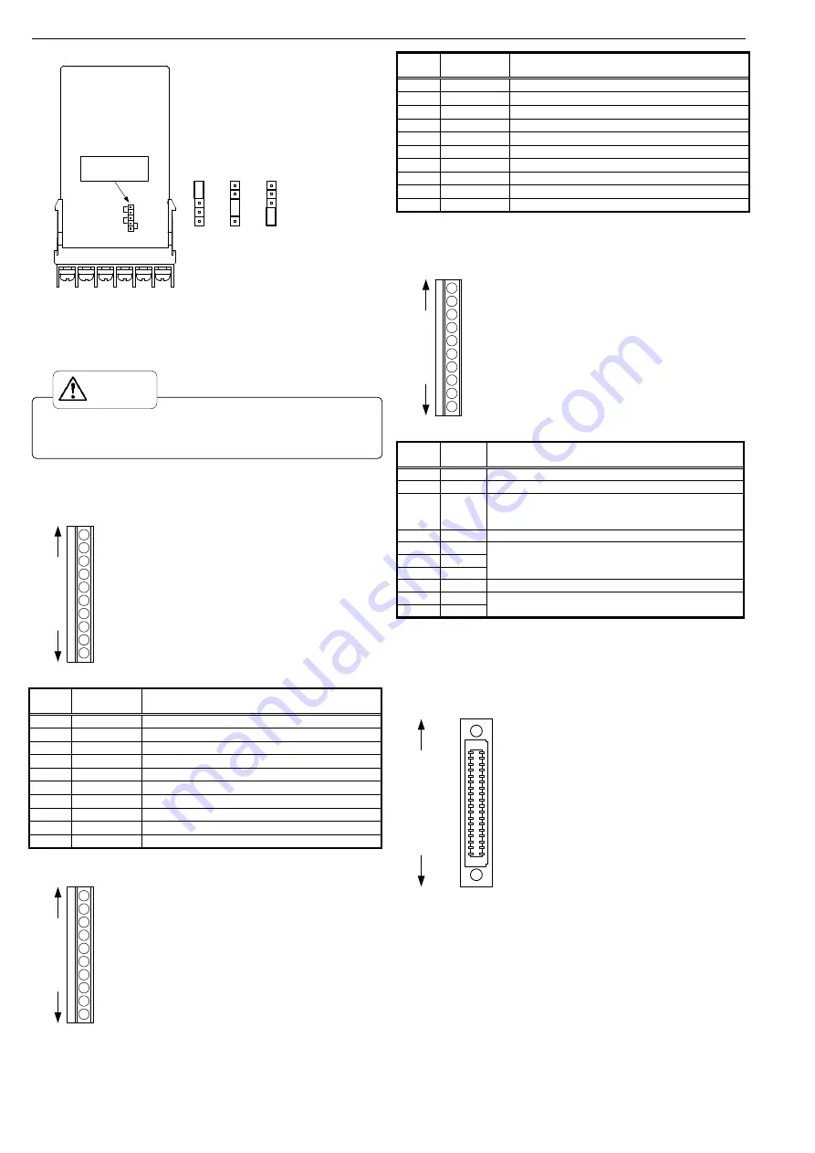
Switch the sensor power switch socket as shown in the diagram below.
+12V
+24V
+10V
CN3
DB range input unit
Sensor power
switch socket
+24V
+12V
+10V
(3)
After completing the switch, install the input unit according to the guides
found on the interior of the main unit case.
(4)
Connect the input unit connector (female) to the main unit connector
(male) ensuring they are firmly connected.
3-4 Comparative Output Connection
3.81mm pitch European terminal board
3-4-1 Relay Output
HH a
1
2
3
4
5
6
7
8
9
10
HH c
HI a
HI c
GO a
GO c
LO a
LO c
LL a
LL c
Adaptable wire: AWG24 to 16
Length of stripped wire: 6 to 7mm
Top
Bottom
Recommended torque : 0.18Nm
Terminal
No.
Name
Details
1
HH a
HH Output relay a-contact terminal
2
HH c
HH Output relay COM terminal
3
HI a
HI Output relay a-contact terminal
4
HI c
HI Output relay COM terminal
5
GO a
GO Output relay a-contact terminal
6
GO c
GO Output relay COM terminal
7
LO a
LO Output relay a-contact terminal
8
LO c
LO Output relay COM terminal
9
LL a
LL Output relay a-contact terminal
10
LL c
LL Output relay COM terminal
3-4-2 Photocoupler Output
HH C
1
2
3
4
5
6
7
8
9
10
HH E
HI C
HI E
GO C
GO E
LO C
LO E
LL C
LL E
Top
Bottom
Adaptable wire: AWG24 to 16
Length of stripped wire: 6 to 7mm
Recommended torque : 0.18Nm
Terminal
No.
Name
Details
1
HH C
HH Output photocoupler Collector terminal
2
HH E
HH Output photocoupler Emitter terminal
3
HI C
HI Output photocoupler Collector terminal
4
HI E
HI Output photocoupler Emitter terminal
5
GO C
GO Output photocoupler Collector terminal
6
GO E
GO Output photocoupler Emitter terminal
7
LO C
LO Output photocoupler Collector terminal
8
LO E
LO Output photocoupler Emitter terminal
9
LL C
LL Output photocoupler Collector terminal
10
LL E
LL Output photocoupler Emitter terminal
3-5 Option Connection
3-5-1 External Control
3.81mm pitch European terminal board
S/H
1
2
3
4
5
6
7
8
9
10
PH
DZ
R.RES
PSEL0
PSEL1
PSEL2
COM
NC
NC
Top
Bottom
Adaptable wire: AWG24 to 16
Length of stripped wire: 6 to 7mm
Recommended torque : 0.18Nm
Terminal
No.
Name
Details
1
S/H
Start/Hold control terminal
2
PH
Peak hold control terminal
3
DZ
Digital zero control terminal
* Becomes effective when parameters settings are set to
external control
4
R.RES
Relay reset control terminal
5
PSEL0
Pattern select control terminals 0 to 2
* Becomes effective when parameters settings are set to
external control
6
PSEL1
7
PSEL2
8
COM
External control common terminal
9
NC
Do not connect anything to these terminals.
Please do not use NC terminals as relay terminals.
10
NC
3-5-2 BCD External Control
1.27mm pitch, one-touch insertion/ejection, 2 piece connector (manufactured
by KEL)
Receptacle Section: 8822E-036-171-F (manufactured by KEL)
(accompanying item)
10
4
8
10
4
2
10
3
8
10
3
2
10
2
8
10
2
2
10
1
8
10
1
2
10
5
1
10
4
4
10
4
1
10
3
4
10
3
1
10
2
4
10
2
1
10
1
4
10
1
1
10
0
4
10
0
8
10
0
2
10
0
1
POL
OVER
PC
D.COM
D.COM
ENA
S/H
PH
DZ
PSEL0
PSEL2
COM
R.RES
PSEL1
COM
Receptacle section adaptable wire
1.27mm pitch universal flat cable
(AWG28)
1
2
35
36
Top
Bottom
Please turn off the device and wait for a minimum of 10 minutes before
commencing any work on the device. Failure to do so may result in
electrocution or fire.
CAUTION


