background image


Vehicle Installation Instructions 


WGD00085 REV B1 


 Page 23 


Radar Interface Cable (Optional) – Purple/Black/Gray connector 

The radar interface cable connects from the radar unit into the radar interface connector on the input 
cable.  Please refer to the specific installation instructions included with the radar interface cable. 

GPS Antenna (Optional) 

The GPS cable has a threaded antenna ferrule and should be attached to the GPS port on the back of the 
DVR.  The antenna end has a magnetic base and may be mounted to the exterior roof, trunk, on the 
vehicle, or may be mounted to the dashboard of the car providing that sufficient view of the sky is 
available.  


Display and Front Combo Camera cables – HDMI/HDMI mini 


Warning:

 HDMI cables are very susceptible to damage and will not worked if kinked or pinched.  Be very 

careful when installing and working around these cables. 

 
Typically the front combo camera cable and the display cable will be run in the same vicinity.  Mark one 
of the cables on both ends to distinguish it from the other.  The standard (larger) HDMI connectors 
connect to the back of the DVR.  Typically, the cables are run along the top of the headliner, down the A-
pillar to wherever the DVR is mounted. 


Note:

 If the HDMI cables are reversed the DVR will not be able to power up via the front panel on/off 

switch.  


Front HD camera HDMI/HDMI mini 

In some installations a separate front and rear camera will be used (the DVR needs 2 cameras to 
function).    A front HD camera can only be added to a DVR that has a REV 2 board.  To see if the DVR has 
a REV 2 board, check the serial number for a 

DVR2

-XXXXXX.  If it has a BDVR, EDVR, then it is not 

compatible.   
 

Rear analog camera HDMI/BNC 

The rear analog camera uses an HDMI (standard) to BNC connection to the rear camera.  A rear camera 
can only be added to a DVR that has a REV 2 board or a Mezzanine card.  If using a Mezzanine card, then 
there will be a VGA cable instead of the HDMI cable to the rear camera.  Use the mezzanine card for 
installations that have more than 1 auxiliary analog camera. 
 

Summary of Contents for 4RE

Page 1: ...4RE Vehicle Installation Instructions WatchGuard Video WGD00085 REV B1...

Page 2: ...e 4RE system in a vehicle 5 Quick Overview of Installation 6 Starting Your Installation 6 Mounting the Wireless Antenna to the Vehicle 7 Mounting the Bullet Radio 10 Connecting the Power Cable to the...

Page 3: ...ount NMO Drill 3 4 Hole 1 WGP01506 KIT Cable Assembly DV 1C 4RE Power Input R A 24 1 WGP412 Cabin Microphone 7 1 WGP412 300 Cabin Microphone Extension Cable 12 1 WGP01832 4RE Cable HDMI Port 2 Backsea...

Page 4: ...tility Knife Torx screwdrivers or bits sizes T20 T15 T10 1 16 hex screwdriver or Allen head wrench Electrical Tape and or heat shrink tubing Zip ties Document Conventions The following conventions are...

Page 5: ...ation poster as a reference guide for the overview of the installation a If you did not receive an installation poster you can download a copy from our website http watchguardvideo com support or call...

Page 6: ...play e Ethernet 6 Install optional cables GPS and Radar 7 Install optional switch for MDC MDT application 8 Mount PoE connector 9 Mount touch display bracket 10 Mount Wireless Microphone 11 Connect an...

Page 7: ...cle Caution There are 2 different types of antenna mounts a thru hole antenna NMO mount which requires drilling a hole in the metal of the vehicle OR a magnetic mount which does not require drilling a...

Page 8: ...to ensure a good ground Figure 6 4 Remove the NMO exterior nut 5 Ensure that the antenna mount ridges come in contact with the bare metal Figure 7 Figure 6 Figure 7 6 Feed the antenna cable connector...

Page 9: ...use a Channel lock pliers as it could damage the NMO nut Instead use an open end wrench Damaging the NMO nut could result in unreliable wireless signal Figure 11 Figure 12 Figure 13 10 Route the anten...

Page 10: ...urposes Common mounting locations are Glove compartment On the front of the Cage Inside the center console There is no mounting hardware included with the Bullet radio It is typical to use zip ties to...

Page 11: ...ng access to the engine bay Use the one that is the easiest to access Ford Crown Victoria factory grommet is on the front foot well on the passenger side Dodge Charger battery is located in the trunk...

Page 12: ...nsion wire to the vehicle battery at this time if possible It is easier to route the chassis ground cable with the rest of the cables The extension cable is not included use an additional cable for th...

Page 13: ...lated silver drain wire and chassis ground wires together Figure 20 and crimp on a ring terminal to be attached to the battery negative ground post Figure 21 Figure 20 Figure 21 10 Crimp the red posit...

Page 14: ...ive and negative wires to the appropriate vehicle battery posts Figure 23 Figure 23 12 Route the power harness inside the engine bay in such a manner that it will not interfere with the vehicle Note L...

Page 15: ...t provides positive 12 volts when the vehicle is ON and 0 volts when the vehicle is OFF There is a fuse link with a 1 amp fuse provided to connect the ignition feed and the ignition sense wire from th...

Page 16: ...o a positive 12 volt switched power source that provides voltage when the overhead lights are activated Figure 25 Note Some emergency light manufacturers use negative 12 volt or ground triggers In tho...

Page 17: ...n Wires The siren input wire consists of two wire connections the green wire is connected to the siren speaker ground feed and the pink wire is connected to the positive siren speaker feed When the si...

Page 18: ...ation this input wire may or may not be used The input should be connected to a device that provides positive 12 volt switched power to be used as an alternate trigger For example the input can be con...

Page 19: ...ut for an administrator to see if an officer was pressing the brake before a crash Figure 28 Several common factory sources for brake light power are as follows Crown Victoria Green wire with red stri...

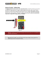
Page 20: ...screw nut bolt Test the wire with a volt meter or multi meter and ensure there is no stray voltage The Chassis Ground cable should not have any more than 025 volts Anything more will cause the DVR to...

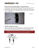
Page 21: ...the labeled holes on the POE adapter and tighten the screws down with a small flat or Philips screwdriver Figure 30a Figure 30a PoE Ethernet Cable Connections There are 2 Ethernet cables included in t...

Page 22: ...thernet cable CAT5E or CAT6 from the PoE switch to the Laptop Ethernet port RJ45 Figure 32 In the figure only the DVR and Wireless Radio are connected Use any of the numbered ports for the Laptop conn...

Page 23: ...lay cable will be run in the same vicinity Mark one of the cables on both ends to distinguish it from the other The standard larger HDMI connectors connect to the back of the DVR Typically the cables...

Page 24: ...mounting locations are Passenger visor post Universal bracket can be mounted almost anywhere side of the console rear of the console on the cage wall etc The cable has a male 8 pin RJ45 on one end and...

Page 25: ...lue the camera mounting button to the windshield using adhesive Ensure that the button is mounted with the bevel towards the windshield and the curved edge pointing down Route the Front Camera HDMI ca...

Page 26: ...Vehicle Installation Instructions WGD00085 REV B1 Page 26 Figure 33c Figure 33d Figure 33e...

Page 27: ...light scoring the side of the button that glues to the windshield using sandpaper Figure 34 No Scoring Scoring applied Figure 34a Figure 34b 2 Clean the area where the button will be placed 3 Place t...

Page 28: ...le to the camera round edge towards the front of the camera Figure 36 38 Figure 36 Figure 37 Figure 38 2 Screw on the thumb screw that holds the cable in place Figure 39 Figure 39 3 Tighten the mounti...

Page 29: ...ehicle to vehicle In this scenario zip ties were used to secure the camera around the cage tubing ensuring that the ties are tight enough that the window frame of the cage will not close and rub again...

Page 30: ...microphone volume in order to listen for the live feed through the display speakers Press STOP to end the recording 8 If equipped connect and test secondary wireless microphone see above 9 Press the...

Page 31: ...ructions WGD00085 REV B1 Page 31 4RE Vehicle Installation Instructions WatchGuard Video 415 Century Parkway Allen Texas 75013 1 800 605 6734 Toll Free Sales 1 866 384 8567 Toll Free Support CustomerSe...

Reviews: