Visit
www.watchguardsystems.com
for full user manual and support
11
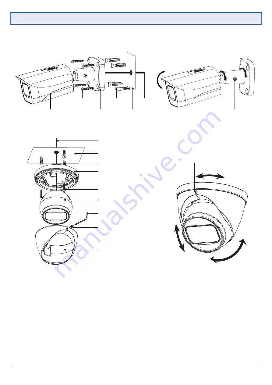
Fig. 3.1:
Mounting diagram for fixed bullet
Camera
Base
Surface
Cables
Self-tapping
screws
Wall plugs
Fig. 3.3:
Mounting diagram for fixed dome
Surface
Wall plugs
Self-tapping screws
Camera
Enclosure
Locking screw
Allen key
Pedestal
Fig. 3.4:
Tri-axis fixed dome adjustment
Fig. 3.2:
Tri-axis fixed bullet adjustment
Locking screw
Locking screw
Cables
NOTE:
Diagrams shown below assume camera to be mounted on masonry. Cameras mounted on drywall (gyprock,
plasterboard, etc.) will require special mounting screws or toggles (not included).
3.2 Mounting Surveillance Cameras (continued)


