Visit
www.watchguardsystems.com
5
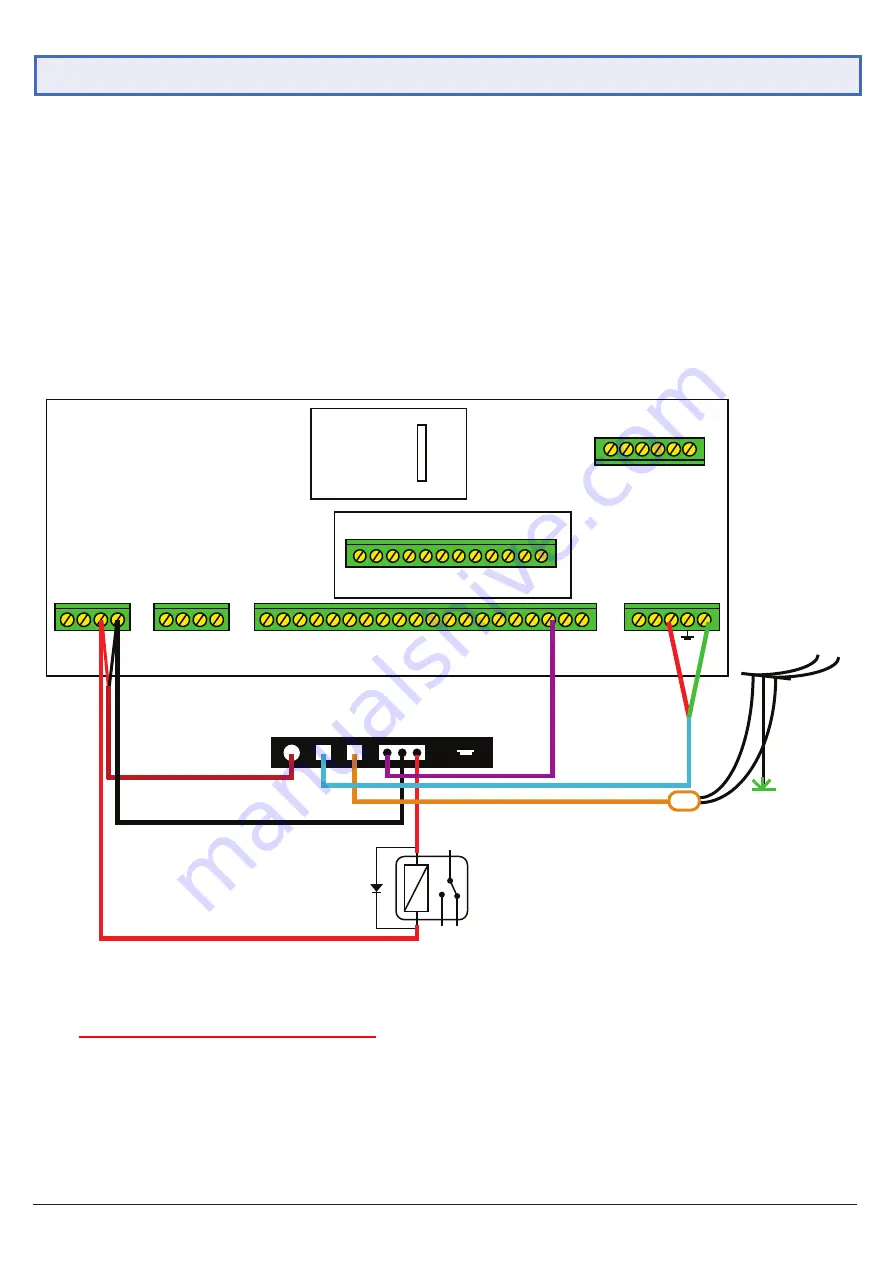
1.5 Alarm Panel Connnection
Now that the communicator has been fully configured, it’s ready to be connected to the alarm panel. For this section, the
Watchguard™ Professional 8 Zone Alarm Panel (WGAP864) will be used as an example.
1. Unplug the communicator from the PC, then unscrew and open the alarm panel.
2. Insert the SIM card into the SIM slot.
3. Connect the communicator in-line with your alarm panel (refer to Fig. 1.4.4).
4. For testing purposes, if you have a monitoring centre, do NOT connect the RJ11 cable yet.
5. Attach the included external antenna to the ANT socket of the communicator.
6. Connect the communicator to a 9~36VDC power supply to turn it on.
Plug In 8 Zone Expander - WGAP864EXP816
9
•
•
•
•
•
10 11
12 13
14 15
16
+
-
D+
•
•
+ -
+
16V
AC
x
-
+
-
D- 1
2 3
4
•
5
6
•
7
•
P
5 4 3 2 1
PROG OUTPUTS
ZONE
ZONE
SIREN
AUX 12V
KEYPAD
ZONE
ZONE
ZONE
ZONE
PHONE
LINE
IN
Voice Module
WGAPX64VM
ZONE
ZONE
ZONE
WGAP864
OP/1 1 Sec Pulse
Arm/Disarm
OP/2 Relay Control
9 36V
DC
Alarm
Panel
Land
Line
USB
OC O/P
1 C 2
8
Fig. 1.5.1:
WGAP864 Alarm Connection Example
WGAP864 alarm configuration: (Must set up these figures otherwise it won't send SMS)
- Location 46, Data 1 = ON (Y)
- Location 51 =
Report Centre
Telephone number (
If no reporting centre, a
ny number is okay)
- Location 61 = 4-digit
report centre account code. (If no reporting centre, enter any 4-digit
non-zero numbers.
)
***
If 0000 is used, SMS function is disabled.
Installers Must Read


