background image


29 

4  Main Screen  


Before operation, please make sure HDD and all the cable connections are properly 
installed.  

 
: Enter Backup window 

: Enter DVR settings 

: Enter DVR search for 
recorded images 

: Login to DVR requires a 
valid username and 
password. 

 
: Open the PTZ control panel 

: Open the Picture controls. 


The Camera Indicator 

blue buttons indicate the 
cameras are connected. And 
the red numbers shows the 

cameras currently being viewed on screen. 
In case of video loss the camera the 
buttons will flash to red and blue. On a 

Single camera view, click on the desired 
button to select a different camera. 

 
: 1 View camera on the screen. 
: 4 View cameras on the screen. 
: 6 View cameras on the screen. 
: 9 View cameras on the screen. 
: 10 View cameras on the screen. 
: 16 View cameras on the screen. 
: Rotate to the next set of cameras.  
: Auto Rotate automatically switching. 
: Large Screen Put camera(s) on full 
screen. 
 

: Manually 
Active or 

Deactivate the relays 


Summary of Contents for EL12004RT

Page 1: ......

Page 2: ...ATION AND CONNECTIONS 20 3 1 Check Unpacked DVR 20 3 2 HDD Installation 20 3 2 1 Choose HDDs 20 3 2 2 Calculate HDD Size 20 3 2 3 HDD Installation 20 3 2 3 1 RTS series 20 3 2 3 2 EL System 21 3 3 CD DVD Burner Installation 22 3 4 Desktop and Rack Mounting 22 3 4 1 Desktop Mounting 22 3 4 2 Rack Mounting 22 3 5 Connecting Power Supply 22 3 6 Connecting Video Input and Output Devices 22 3 6 1 Conne...

Page 3: ...ecord menu 31 4 2 2 2 Basic operation 31 4 2 2 3 Enable disable record 32 4 2 2 4 Enable all channel recording 32 4 2 2 5 Stop all channel recording 32 4 3 Search Playback 33 4 3 1 Search Menu 33 4 3 2 Basic Operation 34 4 3 2 1 Playback 34 4 3 2 2 Accurate playback 34 4 3 2 3 Synchronized playback function when playback 34 4 3 2 4 Digital zoom 34 4 3 2 5 File backup 34 4 3 2 6 Slow playback and f...

Page 4: ...2 4 8 2 PTZ Setup 43 5 MENU OPERATIONS AND CONTROLS 44 5 1 Menu Tree 44 5 2 Main Menu 44 5 3 Setting 44 5 3 1 General 45 5 3 2 Compression 45 5 3 3 Schedule 46 5 3 4 Com Port 46 5 3 5 Network 46 5 3 5 1 PPPoE Connection 47 5 3 5 2 Web connect via Network 48 5 3 5 3 FTP 48 5 3 5 4 NTP 50 5 3 6 Alarm 51 5 3 7 Detect 51 5 3 8 Pan Tilt Zoom 51 5 3 9 Display 51 5 3 10 Default 52 5 4 Search 53 5 5 Advan...

Page 5: ...60 6 ABOUT AUXILIARY MENU 62 6 1 Go to Pan Tilt Zoom Menu 62 6 1 1 AVT Automatic Video Tracking 62 6 2 Preset Tour Pattern Border Function 62 6 2 1 Preset Setup 63 6 2 2 Activate Preset 63 6 2 3 Auto Tour Setup 63 6 2 4 Activate Tour 64 6 2 5 Pattern Setup 64 6 2 6 Activate Pattern Function 64 6 2 7 Border Limit Setup 64 6 2 8 Activate Auto Scan 65 6 3 Dome Menu Control 65 7 WEB CLIENT OPERATION 6...

Page 6: ...Config 78 B Import Config 78 7 6 3 Advance 78 7 6 3 1 Account 78 7 6 3 2 Record Control 79 7 6 3 3 Record Control 79 7 6 3 4 Snap Watermark 80 7 6 3 5 Auto Reboot 80 7 6 4 Extend Function 81 7 6 4 1 ATM POS 81 7 6 4 2 Audio Settings 81 7 6 4 3 DNS Setting 82 7 7 7 7 7 7 7 7 About About About About 82 7 8 Un install Web Control 82 8 PRO SURVEILLANCE SYSTEM 83 8 1 Features 83 8 2 Environment 83 8 3 ...

Page 7: ...7 APPENDIX A HDD CAPACITY CALCULATION 88 APPENDIX B COMPATIBLE USB DRIVE LIST 89 APPENDIX C COMPATIBLE CD DVD BURNER LIST 90 APPENDIX D COMPATIBLE SATA HDD LIST 91 ...

Page 8: ...a reference tool for the installation and operation of your system Here you can find detailed information about the features and functions specific to this DVR series as well as a detailed menu tree Before installation and operation please read the following safeguards and warnings carefully ...

Page 9: ...alified service engineers We are not liable for any problems caused by unauthorized modifications or attempted repair 5 Environment The DVR should be installed in a cool dry place away from direct sunlight inflammable explosive substances and etc 6 Accessories Be sure to use all the accessories recommended by manufacturer Before installation please open the package and check all the components lis...

Page 10: ...irectional talk supported Easy backup methods USB devices CD RW DVD RW and network download Alarm triggering screen tips buzzer PTZ preset e mail FTP upload Smart HDD Management Non working HDD hibernation HDD faulty alarm RAID functionality Powerful networking software Built in web server multi DVR client CMS networking access for remote live viewing recording playback setting system status event...

Page 11: ...era title time video loss camera lock motion detection and recording TV Output Adjustment Adjust TV output color and display zone Audio Audio Input 4 8 16 channel BNC 200 2800mV 30KΩ Bi directional Audio Input 1 channel BNC 200 2800mV 30KΩ Audio Output 1 channel BNC 200 3000mv 5KΩ Audio Compression ADPCM Video Detection Alarm Motion Detection 192 16x 12 detection zones 6 levels of detection sensit...

Page 12: ...SB HDD USB CD RW DVD RW built in IDE Burner network download Network Interface RJ 45 Port 10 100M Network Functions TCP IP DHCP DDNS PPPOE E mail FTP Remote Operation Monitor PTZ control playback system setting file download log information Auxiliary Interface USB Interface 2 ports 1 for mouse 1 for backup RS 232 Watchnet keyboard PC communication RS 485 PTZ control Environmental Power Supply 110V...

Page 13: ...trol Confirm operation 4 Enter ENTER Enter Cursor Selection Cancel cursor selection 5 Cancel EXIT During Playback restore to real time monitor In real time monitor mode it works as the left right direction keys In playback mode turn clockwise to go forward and counter clockwise to go backwards Acts similar to up down direction key in menus In playback mode turn inner dial to perform frame by frame...

Page 14: ...PTZ control and Color Setting 16 Function Key AUX In Search it will change the Display Mode 17 USB connector Used for external storage 1 Front 1 Rear USB mouse connection Left Right Arrow Shift current activated control When in playback mode push these buttons to control the playback bar Up Down Arrow Activate the current control modify setup increase decrease numeral assistant functions such as P...

Page 15: ...h as PTZ menu Switch from multi view to single view When a text box is selected use to input 4 10 Right Shift current activated control When in playback mode push these buttons to control the playback bar In single view switch from 1 camera to another When a text box is selected use to input 3 11 Left Shift current activated control When in playback mode push these buttons to control the playback ...

Page 16: ...2 3 1 RTS series Please refer to 365HFigure 2 3 for real panel information Figure 2 3 2 3 2 RTSL RTSH with Loop Out and Matrix Refer to 366HFigure 2 4 for real panel information Figure 2 4 Note 25 pin or 37 pin interface ...

Page 17: ... 2 3 3 EL Systems Please refer to Figure 2 3 3 for real panel information Figure 2 3 3 2 3 4 Connection Sample Refer to Figure 2 3 4 for a connection sample reference when connecting the DVR Figure 2 3 4 ...

Page 18: ...gure 2 5 S N Name Icon 1 DVR Remote switch Id 2 Cancel Esc 3 Switch View Mode View Stop Play Next Selection Fast Forward Slow Play Play Pause Reverse Play 4 Play Previous Selection 5 Record Record 6 Function Key Aux Left Right Arrow Up Down Arrow 7 Enter Enter 8 Menu Menu 9 Number Pad 0 9 ...

Page 19: ... Left Click In multiple window mode double left click one channel to view in full window Double left click current video again to go back to previous multiple window mode Right Click Exit current menu without saving changes In numeric input box Increase or decrease the numeric value Switch the items in the check box Middle Click Scroll Wheel Page up or page down Move Mouse Select current control o...

Page 20: ...la of total HDD size is Total Capacity MB Camera Amount Recording Hours HDD Usage Per Hour M h H 264 compression is ideal for standalone DVRs It can save more than 30 HDD capacity over MPEG4 When calculating the total HDD capacity estimate the average HDD capacity per hour for each channel For example for a 4 ch DVR the average capacity of HDD usage per hour per channel is 200M h Now if the DVR ha...

Page 21: ...onnect any USB devices Mouse portable hard drive or CD RW to the USB port directly 3 2 3 2 EL System 1 Remove the upper cover of the DVR by removing 4 screws located at the back 3 Screw the HDD into the bracket 5 Connect the IDE cable to the IDE port After HDD installation please check connection of data ribbon and power cord 2 Set the IDE jumper on the HDD to Master 4 Connect the IDE and Power to...

Page 22: ...deep Install the cabinet in well a ventilated location Avoid extreme heat humid or dusty conditions Use a soft dry brush to clean opening outlet cooling fan and etc regularly 3 5 Connecting Power Supply Please check that the input voltage and device power switch on the back match Its recommend to use a UPS to guarantee steady operation DVR life span and other peripheral equipments operation such a...

Page 23: ... at the same time But BNC Video output 2 can display properly with Video Output 1 or VGA Figure 3 2 3 7 Connecting Bi directional Audio Looping Video Matrix NOTE Looping Video Matrix is only for RTSL RTSH system For the 25 pin or 37 pin interface different models include different functions Figure 3 3 3 7 1 Audio Input One Audio Output RTSLH has 16 looping video inputs 1 matrix video output 4 audi...

Page 24: ...eo Output RTS series only Use video matrix output connector during installation to display video sequentially from each video input The unit displays each channel for selected seconds This feature can use to verify camera installation To display video from each connected video source 1 Connect a video monitor to the video matrix output connector 2 Turn the DVR on the monitor and each video matrix ...

Page 25: ...ize the connection between the alarm output port and the load Please refer to 373HFigure 3 7 for more information Figure 3 7 3 7 7 Alarm Input and Output Details Refer to the following sheet and 374HFigure 3 8 for alarm input and output information Parameter Grounding Alarm Ground Ground line Alarm Input 1 2 16 Relay Output 1 2 3 4 NO and C Normally Open and Com 5 NO C and NC Normally Open Com Nor...

Page 26: ...ng external power to the alarm device use the same ground with that of DVR Figure 3 8 3 7 8 Relay Output Description 6 way relay alarm output Provide external power to external alarm device To avoid overloading please read the following relay parameters sheet carefully See below table The controllable 12v can be used to restore the smoke detector Please refer to Figure 3 9 for alarm input module i...

Page 27: ...ies DVR also support NKB operation Operate the DVR from the keyboard controls instead of using the control pad on the front panel of the unit To connect a NKB keyboard to the DVR 1 Assemble the KBD keyboard according to the instructions in its accompanying installation manual 2 Connect the KBD keyboard into one of the RS232 ports on the DVR or through network 3 9 RS 485 When the DVR receives a cam...

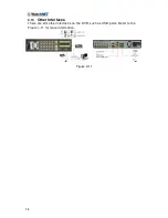
Page 28: ...28 3 10 Other Interfaces There are still other interfaces on the DVR such as USB ports Refer to the 376H Figure 3 11 for more information Figure 3 11 ...

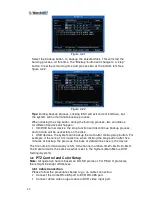
Page 29: ...cted And the red numbers shows the cameras currently being viewed on screen In case of video loss the camera the buttons will flash to red and blue On a Single camera view click on the desired button to select a different camera 1 View camera on the screen 4 View cameras on the screen 6 View cameras on the screen 9 View cameras on the screen 10 View cameras on the screen 16 View cameras on the scr...

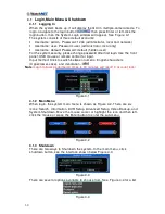
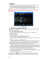
Page 30: ...B mouse or remote control for input Input method Click to switch between numeric English characters Upper lower case and denotation Note Login failures performed 3 times in 30 minutes will result in account lock Figure 4 1 4 1 2 Main Menu When login the system main menu is shown as Figure 4 2 There are six icons Search Information DVR Setup Advanced Setup Video Backup and System Shutdown Move the ...

Page 31: ...ngs Main Menu Setting Display when at full screen logo will be displayed when there is Video Loss or when there is no camera connected When the DVR is recording the red dot on the right hand side of the camera label will appear green dot for motion detection 4 2 2 Manual record Note A proper right is needed to implement the following operations Please make sure the HDDs have been properly installe...

Page 32: ...s will records as previously set Main menu Setting Schedule The corresponding indication light in front panel will turn on Figure 4 7 All Channel Manual Record Please highlight ALL after Manual See Figure 4 8 When system is in manual recording any scheduled settings that are set will be overridden Main menu Setting Schedule See the indicator lights in front panel turns on once the system begins ma...

Page 33: ...ays to go to search menu Click Pause Play button in the remote control Click the Search icon on the Main Screen Click Search in the Main Menu The search interface is shown as below See 386HFigure 4 10 There are three file types R regular recording file A external alarm recording file M motion detection recording file C card and pos test overlay recording file For some special series only There are...

Page 34: ...ocess press any numeral key system can switch to the corresponding channel video of the same time 4 3 2 4 Digital zoom When the system is in full screen playback mode drag the mouse in the screen to select a section and then left click mouse to utilize digital zoom Right click the mouse to exit 4 3 2 5 File backup System supports backup operation during search Put a before file name multiple choic...

Page 35: ...move back frame by frame 4 3 2 8 Backward playback and frame by frame playback Button Illustration Remarks Backward play in playback interface In normal playback mode left click the backwards play button The system will begin backward playback Click backwards play button again and the video will pause Manual playback frame by frame In playback mode push the pause button then slowly turn the jog di...

Page 36: ...detection MD and Alarm Please highlight icon to select the corresponding function Then click the save button the system will go back to the previous menu At the bottom of the menu there is a color bar for reference Green stands for regular recording yellow stands for motion detection and red stands for alarm recording 4 4 1 1 Quick Setup This function allows copying one channel setup to another Af...

Page 37: ... disk There are two ways to playback or search in the redundant disk Set redundant disk s as read only disk or read write disk Main menu Advanced HDD management See 394HFigure 4 13 System needs to reboot to get setup activated Now search or playback file in redundant disk Remove the disk and play it in another PC 4 5 Motion Detect 4 5 1 Go to Motion Detect Menu In the main menu from Setting to Det...

Page 38: ... message in the screen once alarm occurs Please highlight icon to select the corresponding function After completing the setup select the save button The system will then go back to the previous menu Note In motion detection mode copy paste to set channel setup is disabled since the video in each channel may not be the same In 399HFigure 4 15 left click mouse and then drag it to set a region for m...

Page 39: ...0 Alarm output When video loss has occurred the system enables peripheral alarm devices Please highlight icon to enable this function Show message System pops up a message in the screen to alert the user once an alarm has occurred Highlight the icon to enable this function Figure 4 17 4 5 4 Camera Mask Detect When someone viciously masks lens the system can alert the user to guarantee video contin...

Page 40: ... of alarm There are two types of alarm sources local and network input Type Normally open or normally closed Record channel Select the proper channel s to record alarm video At the same time the setting for alarm recording in the schedule interface Main Menu Setting Schedule and select schedule record in the manual record interface Main Menu Advance Manual Record is needed Latch This allows the se...

Page 41: ...channel start time and end time Click the add button system will begin searching All matched files will be listed below System will automatically calculate the capacity needed See 408HFigure 4 21 The systems will only backup files with a before channel name Use AUX or left click button to remove the When the system completes the backup procedure a dialogue box prompting for confirmation of a succe...

Page 42: ...nd no data will be accessible on the disk USB devices the system can backup the data after clicking stop button For example if there is a 10 minutes file when clicking the stop button after five minutes of backup the previous 5 minute of data will be save in the device The file name format usually is SN_CH channel number timeY M D H M S The Date format is the same as what is set in the System Main...

Page 43: ...rd In the main menu click setting and then click Pan Tilt Control button The interface is shown as in 410HFigure 4 23 Set the following items Channel Select the current camera channel Protocol Select corresponding PTZ protocol such as DH SD1 Address Default address is 1 Baud rate Select corresponding baud rate Default value is 9600 Data bits Select corresponding data bits Default value is 8 Stop b...

Page 44: ...below Figure 5 1 There are six icons in total Search Information Setting Advanced Backup and Shutdown Move the cursor to highlight the icon then left click to enter the sub menu Figure 5 1 5 3 Setting In main menu highlight the setting icon and double click with the mouse The system setting interface is shown as below See 444HFigure 5 2 Figure 5 2 ...

Page 45: ...ntrol several DVRs give the DVR a number to manage each one Video Standard Two formats NTSC and PAL Auto Logout Set an auto logout interval once a logged in user remains inactive for a specified time Ranges from 0 to 60 minutes Default 10 minutes Note Since system time is very important do not modify time casually unless there is a need to do so After completing setup select the save button this w...

Page 46: ...corded videos Please highlight icon to select the corresponding function Figure 5 4 5 3 3 Schedule Please refer to chapter 4 4 Schedule 5 3 4 Com Port RS232 interface is shown as below Here are five items See Figure 5 5 Function There are various devices that can be selected Baud Rate Select proper baud rate Data Bits Select proper data bit Stop Bits There are three values 1 1 5 2 Parity There are...

Page 47: ...ne of the three and then click properties button to go to setup interface Authorization Click authorization button please highlight icon to enable IP authentication function When this function is enabled only IP in the list can login this DVR See 449HFigure 5 7 After completing the setup select the save button to go back to the previous menu Figure 5 6 Figure 5 7 5 3 5 1 PPPoE Connection Enable PP...

Page 48: ...e from the IPS and server IP PC with DDNS Click the Save button system prompts for reboot to get all setup activated After rebooting open IE and input as below http DDNS server IP virtual directory name webtest htm ex http 10 6 2 85 DVR _DDNS webtest htm Now DDNSServer web search page can be opened 5 3 5 3 FTP Download or buy an FTP service tool Such as Serv U FTP SERVER to use the FTP service Ple...

Page 49: ... functionality The DVR can now upload alarm video and motion detection video via FTP Please note when using this function please make sure current upload channel is in motion detection or alarm record status and there is video available Input FTP server address port and etc Figure 5 11 File length Upload files length When video is smaller than the actual file length it will upload the whole file W...

Page 50: ...3 Host IP Input the PC address Port This series DVR supports TCP transmission only Default port value is 123 Update interval minimum value is 15 Unit Minutes Time zone select the corresponding time zone Here is a time zone reference table to refer to when selecting the correct area City Region Name Time Zone London GMT 0 Berlin GMT 1 Cairo GMT 2 Moscow GMT 3 New Delhi GMT 5 30 Bangkok GMT 7 Beijin...

Page 51: ...ncy Here the menu transparency can be adjusted The value ranges from 128 to 255 Channel name Here the channel name can modified Please note any modifications here only apply locally to the DVR The opening of the web or client end is needed to refresh the channel name Time display Toggle if time is to be displayed Channel display Toggle if the channel name is to be displayed Overlay information Sys...

Page 52: ...60HFigure 5 16 Select all General Encode Schedule RS232 Network Alarm Detect Pan tilt zoom Display Channel name Please highlight icon to select the corresponding function After completing setup select the save button this will go to the previous menu Warning System menu color language time display mode video format IP address user account will not maintain previous setup after default operation Fi...

Page 53: ...more redundant HDD s Please note that at least one read write disk is needed otherwise the system will not record video For detailed information refer to chapter 4 4 Schedule After completing setup select the save button the system will need to reboot to perform any changes Figure 5 18 Select the Alarm Set button the interface is shown as below See 463HFigure 5 19 Please highlight icon to select t...

Page 54: ...pts two levels of management group and user No limit to group or user amount For group or user management there are two levels admin and user The user name and group name can consist of eight bytes One name can only be used once There are three default users admin user and hidden user default Hidden user default is for system interior use only and cannot be deleted When there is no login user hidd...

Page 55: ...ch item After completing setup select the OK button this will go to the previous menu Figure 5 233 5 5 7 Video Matrix For RTSL Series and RTSH Series Some series DVR have the matrix and loop outputs 5 5 7 1 Loop outputs They are just the same with video distributors There are 16 ch video loop outputs from our DVR The DVR video output can connect with other devices such as TV walls analog matrix an...

Page 56: ...r loop outputs there are 16 ch loop outputs Blue for matrix outputs there are 4 ch matrix outputs White for bi direction talk one is for audio in and the other is for audio out Figure 5 255 5 5 7 5 Matrix setup 5 5 7 5 1 Enter the Menu of Video Matrix In the menu from Advanced to Video Matrix See 471HFigure 5 266 Figure 5 266 5 5 7 6 Video Matrix Interface and Application The video matrix interfac...

Page 57: ...matrix output will go to tour as was set in the Alarm setting Main Menu Setting Alarm See 474HFigure 5 28 Alarm tour has higher priority than single tour during this period single tour will stop After alarm activation tour the matrix output will continue single tour Figure 5 28 5 5 7 7 Examples A Example one In 475HFigure 5 290 matrix outputs 1 2 3 tour between all cameras of the DVR Matrix output...

Page 58: ...tion BPS Data Stream Statistics Log Version and Online Users See 477HFigure 5 312 Figure 5 312 5 6 1 Hard Disk Information This section lists hard disk type total space free space video start time and status See 478HFigure 5 323 Note Please remove any defective hard disks before adding a new one If there is a hard disk conflict please check that hard disk time and system time are the same Please g...

Page 59: ... is current working disk If disk is damaged system shows as Figure 5 323 5 6 2 BPS View the current video data streams KB s and occupied hard disk storage MB h See 479HFigure 5 334 Figure 5 334 5 6 3 Log Systems log file can be viewed here System would list the following information See 480HFigure 5 345 Figure 5 345 ...

Page 60: ...ure 5 367 Users can be disconnected or blocked here if the login user has proper system privileges Figure 5 367 5 7 System Shutdown Select System Shutdown a pop up dialogue box will appear See 483HFigure 5 378 Logout Menu User Logs current user out In next login the password would be needed Restart Application Restart the DVR application Shutdown Shuts down the DVR and turns off power Restart Syst...

Page 61: ...61 Figure 5 378 ...

Page 62: ...PTZ by clicking and dragging the mouse in the direction that is needed Figure 6 1 6 1 1 AVT Automatic Video Tracking In the middle of the eight direction arrows there is a AVT See 488HFigure 6 2 Click this button and the system will go to single screen mode Drag the mouse in the screen to adjust section size This will utilize the PTZ automatically Figure 6 2 See the table on the next page for refe...

Page 63: ...ure 6 4 In Figure 6 1 use the eight direction arrows to adjust camera to the proper position In 496HFigure 6 3 select the Preset button and input the preset number The interface is shown in 497HFigure 6 5 Now the preset can be added to one tour Figure 6 5 6 2 2 Activate Preset In 498HFigure 6 4 input the preset number in the No blank and select the Preset button 6 2 3 Auto Tour Setup In 499HFigure...

Page 64: ...to 505HFigure 6 7 and click the End button All these operations can be saved as pattern 1 Figure 6 7 6 2 6 Activate Pattern Function In 506HFigure 6 4 input mode value in the No blank and select the Pattern button 6 2 7 Border Limit Setup In 507HFigure 6 3 select the Limit button The interface is shown as in 508HFigure 6 8 Please go to Figure 6 1 use direction arrows to select camera left limit an...

Page 65: ...op button Select the Stop button to terminate the scan operation 6 3 Dome Menu Control In 512HFigure 6 4 select the Page Switch button the interface is shown as below See 513HFigure 6 9 Select menu to enter the dome menu The direction arrows here are to control the dome menu Select the Page Switch button the system will go back to Figure 6 1 Figure 6 9 ...

Page 66: ...eing the DVR s IP address to check the connection Usually the return TTL value should be less than 255 7 2 Login and logout Open IE and input the DVR address in the address column For example if the DVR IP is 10 1 27 200 then please input http 10 1 27 200 in the address column Note A warning may pop up asking to want to install webrec cab control Click the yes button If downloading the ActiveX con...

Page 67: ...login username is admin and password is 1234 Note For security reasons please modify the password after the first login 7 3 Video After login the interface is shown as below See 7 3 Figure 7 3 Input your IP address here Login Window ...

Page 68: ...w channels full screen or change the quality Preview window 1 16 view per window Watch 4 views in 1 window Color Settings change the color settings per window Brightness contrast saturation and hue can be adjusted here Path Settings Recording path Picture path and reboot can be found here PTZ Control Here the PTZ movement can be controlled Before operating please make sure the correct PTZ protocol...

Page 69: ...re operating this function please make the PTZ protocol are set properly Main menu Setting Pan tilt Zoom Figure 7 3 Note This will only work while viewing using Real Time Monitoring mode Clicking the arrow down button in 524HFigure 7 3 will show the interface shown below Figure 7 4 In 526HFigure 7 4 click the PTZ SET button to see the following dialogue box below See 527HFigure 7 5 AVT is 3D posit...

Page 70: ...re 7 3 to implement camera operation Then click stop record button to set the pattern 7 3 1 3 Preset In Figure 7 5 move the camera to the desired location and then input preset value Click add button to save the preset 7 3 1 4 Auto tour In Figure 7 5 input auto tour value and preset value Click add button to add one preset in the tour Repeat the above procedures to add more presets in one tour 7 3...

Page 71: ... video Figure 7 6 In the search result interface one or more files to download to the local PC can be selected The playback bar is shown as below See Figure 7 7 Figure 7 7 7 5 1 Download One or more files can be selected to download and then click the download button A dialogue box will appear asking for specific directory See 535H Figure 7 8 Then the file name can be selected and click Save to sa...

Page 72: ...181643 6 o clock 16 minutes 43 seconds 7 6 Config Click the Config button to enter the DVR s configurations System Info Setting Advanced Extended Function 7 6 1 System Info Here the basic information of the system can be viewed See Figure 7 10 such as Version shows the system features and bios version HDD info shows HDD status free space and capacity Log Show the systems logs ...

Page 73: ...e general button the interface below will be shown Here file length can be change And choose overwrite the previous file or stop recording when disk is full 7 6 2 2 Encode Change the DVR settings for quality camera name FPS resolution disable enable audio ...

Page 74: ...he schedule thru the remote connection Figure 7 11 Tip After finishing the setup for one channel click Save as button system pops up the following interface See 523HFigure 7 12 Copy one channel setup to other channels Figure 7 12 7 6 2 4 RS232 Change the COMPORT setting thru the Web ...

Page 75: ...75 7 6 2 5 Network Network parameter setup interface is shown below This is used to modify DDNS PPPoE Email DDNS settings 7 6 2 6 Multi DDNS Use This Parameters if using Multiple DDNS sites ...

Page 76: ...76 7 6 2 7 FTP Enable Disable FTP capabilities set the FTP parameters FTP Schedules 7 6 2 8 Alarm Change the Alarm in parameters of the DVR ...

Page 77: ...Event Motion Detect settings Set the re action of the system if motion is detected 7 6 2 10PAN TILT ZOOM Change the COMPORT parameters of the system 7 6 2 11 TOOL Create a backup of the configuration of the system Figure 7 6 1 ...

Page 78: ... extension name is cfg B Import Config Click Import Config button in Figure 7 6 2 1 select the file to load a previously backed up configuration Click the Open button to updated the system setup 7 6 3 Advance Modify Advance settings of the DVR 7 6 3 1 Account Add Delete User and Group Modify User and Groups rights and change password ...

Page 79: ...t the Alarm output channel Alarm output channel can not support large overload Use less than 1A Too heavy current may result in relay damage Please use contactor if necessary Figure 7 14 7 6 3 3 Record Control Please select the HDD first and then the items on the right become valid Select the option that is needed and then click HDD control The DVR begins restarting ...

Page 80: ...80 7 6 3 4 Snap Watermark Please note this function is only supported on special series DVR 7 6 3 5 Auto Reboot Enable the auto restarting of the DVR and the auto delete of old files function ...

Page 81: ... 7 6 4 Extend Function Change the parameters of the Extended Function of the DVR 7 6 4 1 ATM POS Set the input DATA of the POS system of the DVR 7 6 4 2 Audio Settings Change the audio settings of the DVR ...

Page 82: ...tton to view current web client information 7 8 Un install Web Control There are three ways to un install web control From start click run and then input order regsvr32 u WebRec ocx Use web un install tool Uninstall Web bat to un install web control By clicking the link http www viewdvr com uninstall 20web bat ...

Page 83: ...tiple device upgrade simultaneously E map and network backup support 8 2 Environment We recommend the following configuration Hardware CPU P4 2 0G Display card support hardware zoom such as ATI TNT2 PRO We recommend ATI9800 or above dual channel 128M 128bit Network card 100M Software For client end we recommend Windows 2000 or Windows XP 8 3Overview Multiple client main window is shown as in 574HF...

Page 84: ...ingle window four window six window eight window nine window sixteen window Section 4 This section displays data flux and CPU status Section 5 There are four function buttons PTZ Color setting Device Plan Management 8 4 More Details Please refer to the Professional Surveillance System User s Manual for more information ...

Page 85: ...ard Control keyboard is very convenient for multi DVR control menu options and PTZ control Select Keyboard Control from system Setting RS232 Function Then set the concerning attributes such as the protocols Connect the DVR RS232 port to shifter 25 pin RS232 port and then set the proper control addresses for all connected DVRs Now input DVR control address and use keyboard keys to set menu or contr...

Page 86: ...fespan 6 I cannot see video signal on one channel while the other channels are ok Check the video cable connection You can connect camera video cable directly to monitor to test If there is still no signal there may be a problem with camera or video cable If there is a video signal please contact your local suppliers for help 7 I cannot use my remote controller Check ACT light on the front panel i...

Page 87: ...uch as keyboard matrix control decode card alarm input and output equipment alarm server and access control system Slight differences may be found in user interface All the designs and software here are subject to change without prior written notice Please visit our website for more information ...

Page 88: ...age capacity i m which is storage of each channel needed unit Mbyte i m i q i h i D 2 In the formula i h means the recording time for each day hour i D means number of days for which the video shall be kept Step 3 According to Formula 3 to calculate total capacity accumulation T q that is needed for all channels in the DVR during scheduled video recording c i i T m q 1 3 In the formula c means tot...

Page 89: ...m 1G Sandisk Cruzer Freedom 2G Kingston DataTraveler Ⅱ 1G Kingston DataTraveler Ⅱ 2G Kingston DataTraveler 1G Kingston DataTraveler 2G Maxell USB Flash Stick 128M Maxell USB Flash Stick 256M Maxell USB Flash Stick 512M Maxell USB Flash Stick 1G Maxell USB Flash Stick 2G Kingax Super Stick 128M Kingax Super Stick 256M Kingax Super Stick 512M Kingax Super Stick 1G Kingax Super Stick 2G Netac U210 12...

Page 90: ...ersion to ensure the accuracy of the table below And you can use the USB cable with the model recommended to set USB burner Manufacturer Model Interface Type Sony AW G170S SATA DVD RW Samsung TS H653A SATA DVD RW Panasonic SW 9588 C SATA DVD RW Sony DRX S50U USB DVD RW BenQ 5232WI USB DVD RW ...

Page 91: ...e Barracuda 11 ST3500320AS 500G SATA Maxtor DiamondMax 20 STM3320820AS 320G SATA Maxtor DiamondMax 20 STM3250820AS 250G SATA Maxtor DiamondMax 21 STM3160211AS 160G SATA Maxtor DiamondMax 21 STM380211AS 80G SATA Maxtor DiamondMax 21 STM340211AS 40G SATA Western Digital Caviar SE WD3200JD 320G SATA Western Digital Caviar SE WD3000JD 300G SATA Western Digital Caviar SE WD2500JS 250G SATA Western Digi...

Reviews: