background image

18

Care, Maintenance and Parts

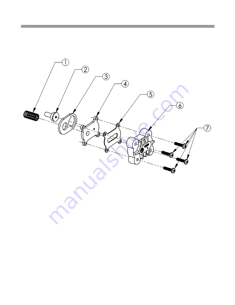
Figure 13 - Injector Assembly

PART#

DESCRIPTION

QUANITY

1     93810

Injector Screen                       

1

2     93223

Injector Throat                         

1

3     93220

Injector Seal                                      1

4     93221

Injector Nozzle      

1

5     93232

Top Injector Seal  (Thin)                    1

6     93222

Injector Cap

1     

7     90807

Screw

4

93501 includes all of the above.

Summary of Contents for 550

Page 1: ...INSTALLATION AND SERVICE MANUAL WaterBoss 4343 S Hamilton Road Groveport Ohio 43125 Model 550 700 and 900 Water Softeners Version 4 ...

Page 2: ...ING THE 4 BUTTON CONTROLLER 13 ADVANCED SETTINGS FOR THE 4 BUTTON CONTROLLER 14 CARE MAINTENANCE AND PARTS 16 SPECIFICATIONS CAPACITY CHART 25 TROUBLESHOOTING 26 LIMITED WARRANTY 28 NOTES 29 Table of Contents When calling the HelpLine please have this guide and the serial number available From 8 am to 5 pm EST call 1 800 437 8993 Your serial number may be found on top of your valve assembly ...

Page 3: ...rial number may be found on top of your valve assembly See figures 2 3 Date of Installation __________________________________ Model Number _____________________________________ Serial Number ______________________________________ Returned Limited warranty Card Date ___________________ 1 Questions When calling the HelpLine please have this guide and the serial number available From 8 am to 5 pm ES...

Page 4: ... can switch to a salt substitute at any time or vice versa If potassium chloride is used in place of nugget or pellet salt increase your hardness setting by 12 multiply by 1 12 Do not use Potassium Chloride if there is iron in your water 3 Should your electricity be turned off for any reason you must reset the time of day if you programmed your appliance for delayed regeneration see page 14 4 Prot...

Page 5: ... installer must provide an adequate air gap or a siphon break See figure 1 5 Electricity The transformer supplied is a standard 120 volt 60 cycle A C for USA or 220 volt 50 cycle A C for outside the USA See figure 8 6 Water Quality If the water supply contains sulfur bacteria iron bacteria tannins algae oil acid or other unusual substances then unless the appliance is represented as being capable ...

Page 6: ...hrenheit Please see specification on page 25 3 Do not allow soldering torch heat to be transferred to valve components or plastic parts See Installation Tip page 6 4 Do not overtighten plastic fittings 5 Do not place appliance right up against a wall which would deny access to plumbing See figure 1 6 Do not install the appliance backwards Follow arrows on inlet outlet See figure 2 7 Do not plug th...

Page 7: ... to untreated water when required i e for lawn and gardening purposes Also see figures 4 through 6 Caution If less than 10 feet of pipe connect the water treatment appliance s to the water heater then a Check Valve must be installed between the water treatment appliance and the water heater Install the Check Valve as close to the water heater as possible 5 Reference Illustrations Figure 1 Installa...

Page 8: ... small void areas that may exist between the threads When the joint is complete there will be a small bead of sealant at the fitting interface indicating a properly joined connection 2 When preparing copper fittings it is always advisable to use a union where there is a threaded connection to facilitate repairing a potential leak in one of your soldered joints 3 To prevent heat damage to the plast...

Page 9: ...gure 5 In Bypass Position p u s h p u l l for service or bypass Optional Bypass Valve Part 93884 may be available through your local hardware store plumber or call our HelpLine 1 800 437 8993 From 8 am to 5 pm EST to order Figure 6 In Service Position ...

Page 10: ...ormer into an outlet that is controlled by on off switch Figure 7 OVERFLOW CONNECTION 1 2 I D When calling the HelpLine please have this guide and the serial number available From 8 am to 5 pm EST call 1 800 437 8993 Your serial number may be found on top of your valve assembly ...

Page 11: ...9 Reference Illustrations Figure 10 ADDING SALT TO THE BRINE CABINET 2 GALLONS Figure 9 ...

Page 12: ...easing accumulated hardness and iron 3 Slow rinse A slow up flow rinse process then flushes out the brine hardness and iron 4 Second up flow backwash This up flow backwash flushes out any remaining brine solution and sediment from cycle 2 5 Downflow soft water brine refill Soft water is directed to the brine cabinet to prepare the brine for the next regeneration sequence 6 Return to service Regene...

Page 13: ...han the control valve See figure 1 3 Flushing Before placing your appliance in service it is very important to flush the cold water lines of any debris Turn on water supply open the nearest cold water tap and let the water run for 2 to 3 minutes or until the water flows clear Then put the by pass in the Service position See figures 4 through 6 4 Check Leaks Close faucet and check for leaks If leak...

Page 14: ... result is still 25 grains per gallon call your HelpLine Or contact the company below to test for hardness iron and pH WATERSCREEN National Testing Laboratories Inc 1 800 458 3330 9 am 5 pm EST If you feel you have an abnormal amount of iron push the powerClean button for Models 700 and 900 only Also be sure to use salt with an iron cleaning additive Be aware that model Model 550 for municipally s...

Page 15: ...kly advance through the regeneration cycles press and hold the Regenerate button for 2 seconds Wait for the cycle to begin after 20 seconds press and hold the Regenerate button until the cycle number changes about 2 seconds Each cycle can be advanced in this manner 4 waterMizer The waterMizer wheel will turn whenever water is being used See figure 9 5 REGENERATE To start an immediate regeneration ...

Page 16: ... a specific time e g at 2 am when less water is being used Demand Mode triggers a regeneration as soon as softening capacity is exhausted Pressing and releasing the SET button will advance programming to the next step Default is Demand Mode 4 96 Hours is now displayed Pressing and releasing the CHANGE button will toggle this on and off If 96 Hours is selected the unit will work no more than 4 days...

Page 17: ...the unit into operation Default is 2 AM PROGRAMMING IS NOW COMPLETE 4 Button Error Descriptions E1 Home magnet not found Cycle power by unplugging the transformer and plugging it back in and it will look for Home again E2 Motor not plugged in Plug motor in and cycle power If it is plugged in then motor wiring or the motor plug is defective E3 Home offset error Disk didn t start in proper home loca...

Page 18: ...Control Assembly 1 54540 700 Computer Control Assembly 1 54540 900 Computer Control Assembly 1 4 93245 12V Transformer Power Cord 1 5 54303 Cabinet 550 700 1 54309 Cabinet 900 1 6 54305 Support Panel 1 7 93530 CITY Media tank empty fill plug 550 only 1 93530 Media tank empty 700 only 1 95505 Media tank empty 900 only 1 7 Figure 11 ...

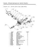
Page 19: ...5 93272 O Ring Model 550 only 2 6 93808 O Ring 2 7 90828 O Ring 1 8 95301T JG Drive End Cap Assembly 1 9 93870 Screw 4 10 93848 3 8 Brine Line 7 1 11 93501 Injector Assembly 1 12 93835 Sleeve 2 13 93524 Drain End Cap Barbed Model 700 and 900 only not shown 1 90614 3 0 Drain End Cap Assembly Model 550 only 1 14 93809 Screw 2 15 V185 Drain Fitting 1 2 MNT x Barb Model 550 only 1 16 93842 Drain Line ...

Page 20: ...ector Assembly PART DESCRIPTION QUANITY 1 93810 Injector Screen 1 2 93223 Injector Throat 1 3 93220 Injector Seal 1 4 93221 Injector Nozzle 1 5 93232 Top Injector Seal Thin 1 6 93222 Injector Cap 1 7 90807 Screw 4 93501 includes all of the above ...

Page 21: ...Assembly 19 PART DESCRIPTION QUANITY 1 54131 3 4 IO Adapter 1 2 90232 Turbine Sensor Cap 1 3 90809 Sensor Cap Screw 1 4 93858 Turbine Sensor Assembly 1 5 90522 Turbine Assembly 1 6 93229 Flow Director 1 7 93838 O Ring 2 54510 includes all of the above ...

Page 22: ...3238 Drive Gear 1 5 90809 Screw Cam Cover 2 6 93219 Piston Slide Cam Cover 1 7 93217 Piston Slide Cam 1 8 93583 Drive End Cap 1 9 93216 Piston Slide 1 10 90818 Screw 2 11 93601 JG Brine Valve Housing Ass bly 1 12 90821 O Ring 1 13 54502 Magnet Disk Assembly 1 14 90828 O Ring 1 15 93808 O Ring 1 16 93522 A Drive Piston Ass bly 1 17 93839 Drain Gasket 1 ...

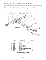
Page 23: ...ston Assembly 1 includes O ring Spring 2 90821 O ring 1 3 93260 Housing 1 4 93878 Quad Ring 1 5 93254 Quad Ring Retainer 1 6 90843 5 pm Flow Control 1 7 93805 O ring 1 8 93243 JG Housing Cap Assembly John Guest 1 9 200199 3 8 Locking Clip 1 10 90807 Screw 2 Concave Side 93601 JG includes all of the above ...

Page 24: ...Care Maintenance and Parts Figure 17 Safety Shutoff Assembly 22 PART DESCRIPTION QUANITY 1 54226 Safety Shutoff 1 2 54227 Float 1 3 54228 Air Check 550 700 1 4 54229 Air Check 900 1 ...

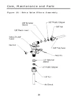
Page 25: ...23 Care Maintenance and Parts Figure 18 Brine Valve Elbow Assembly ...

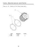
Page 26: ...Care Maintenance and Parts Figure 19 Bottom Fill Plug Assembly 24 PART DESCRIPTION QUANITY 1 90238 Fill Plug 1 2 90819 O ring 2 ...

Page 27: ... Weight Approximate lbs 6 5 17 800 7 5 27 000 5 0 11 500 70 90 25 10 ppm 10 ppm 0 7 7 7 25 Specifications Capacity Chart 2 5 10 500 6 0 24 000 1 25 5 000 120ºF 120ºF 120ºF 10 5 X 14 I D 10 5 X 21 I D 10 5 X 14 I D 16 gpm 15 10 gpm 14 5 10 gpm 15 3 2 4 0 3 2 2 0 2 0 3 0 20 120 20 120 20 120 5 5 5 1 1 2 4 Button 4 Button 4 Button 33 48 27 18 38 9 25 33 25 16 27 15 Demand Demand Demand 120 lbs 160 lb...

Page 28: ...n the sensor chip If light turns clean or replace turbine If no light replace sensor Repair the leak Run water Verify flashing light Plug in transformer Check power source Make sure outlet is not controlled by a switch Test with volt meter for 12 VAC at control If 0 VAC replace trans former No salt in brine cabinet Sediment in brine tank has plugged the brine line and air check Drain line is pinch...

Page 29: ...upply See specifications page 25 Defective circuit board fig 9 Computer control not attached properly Foreign object in valve body Broken valve assembly Motor running Magnet disc not turning page 20 Restricted frozen or pinched drain line Plugged brine line brine line flow con trol or air check page 21 22 Plugged injector assembly page 18 Sticking brine refill valve Magnet disc defective Defective...

Page 30: ...hese substances in the product specifications other special treatment of the water supply must be used to remove these substances before they enter this product Otherwise WaterBoss shall have no obligations under this warranty This warranty does not cover damage to a part or parts of the appliance from causes such as fire accidents freezing or unreasonable use abuse or neglect by the owner This wa...

Page 31: ...29 Notes When calling the HelpLine please have this guide and the serial number available From 8 am to 5 pm EST call 1 800 437 8993 Your serial number may be found on top of your valve assembly ...

Page 32: ... 1998 WaterBoss P O Box 298 Groveport OH 43125 LITHO USA Form 93966 Version 4 RV0403WAL24M U L ...

Reviews: