background image

DIAGNOSTICS 


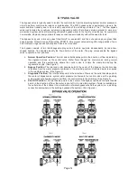
STEP  5D 

- Volume, 63-day usage history: This display shows day 1 

                                         (for yesterday) and flashes the volume of water treated yesterday.    
                                         Pressing the 


button will show day 2 (which would be the day            

                                         before yesterday)  and  flashes the volume of water treated on that 
day. Continue to press the 


button to show the maximum volume of water treated for the 

last 63 days. If a regeneration occurred on the day the word “REGEN” will also be displayed. 
This display will show dashes if a water meter is not installed. Press the NEXT button at any 
time to go to Step 6D. Press REGEN to return to previous


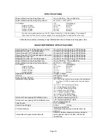
STEP 4D 

– Volume, reserve capacity used for last 7 days: If the  

                                          valve is set up as a softener, a meter is installed and Set Volume  
                                          Capacity is set to “Auto,” this display shows 0 day (for today) and 
                                          flashes the reserve capacity. Pressing the 


button will show day 

1 (which would be yesterday) and flashes the reserve capacity used. Pressing the 


button 

again will show day 2 (the day before yesterday) and the reserve capacity. Keep pressing the 


button to show the capacity for days 3, 4, 5 and 6. The 


button can be pressed to 

move backwards in the day series. Press the NEXT button at any time to go to Step 5D. Press 
REGEN to return to previous step.


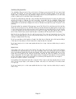
STEP 1D 

– Press 


and 


simultaneously for three seconds. If screen in step 2D does not 

appear in  5 seconds the lock on the valve is activated. To unlock press 

, NEXT, 

, and 

CLOCK in sequence, then press 


and 


 simultaneously for 3 seconds. 


STEP 2D 

–  Days, since last regeneration: This display shows the days since the last 

regeneration occurred.  Press the NEXT button to go to Step 3D. Press REGEN to exit 
Diagnostics. 


STEP 3D 

– Volume, since last regeneration: This display shows the volume of water that has 

been  treated since the last regeneration. This display will equal zero if a water meter is not 
installed. Press the NEXT button to go to Step 4D. Press REGEN to return to previous step. 

STEP 2D 


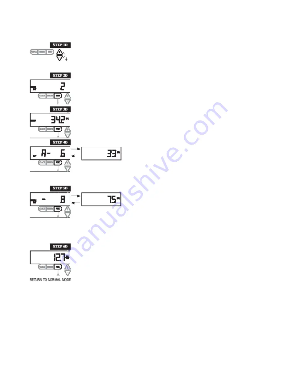
STEP 6D 

– Flow rate, maximum last seven days: The maximum flow rate in gallons per minute 

that  occurred in the last seven days will be displayed. This display will equal zero if a water 
meter is not  installed. Press the NEXT button to exit Diagnostics. Press REGEN to return to 
previous step.


When desired, all information in Diagnostics may be reset to zero when the valve is installed in a new location. 
To reset to zero, press NEXT and  buttons simultaneously for 3 seconds and release. Press  and   
simultaneously for 3 seconds to reset diagnostic values to zero. 

Page 9 

Summary of Contents for PLATINUM SERIES

Page 1: ...TECHNICAL GUIDANCE IT IS STRONGLY RECOMMENDED THAT QUALIFIED DEALER SERVICE PERSONNEL BE CONTACTED IN THE EVENT OF AN UNKNOWN INTERRUPTION OF SERVICE OR APPARENT PRODUCT MALFUNCTION AN ANNUAL PREVENT...

Page 2: ...ngs 4 Installer Display Settings 6 Softener System Setup 6 Softener Setting Options 8 Diagnostics 9 Troubleshooting 10 Installation 12 Bypass Valve 14 Specifications 15 Quick Reference Specifications...

Page 3: ...o ring seals After completing any valve maintenance involving the drive assembly or the drive cap assembly and pistons press and hold NEXT and REGEN buttons for 3 seconds or unplug power source jack f...

Page 4: ...days left before the system goes through a regeneration cycle Capacity remaining is the gallons that will be treated before the system goes through a regeneration cycle Pressing the button while in t...

Page 5: ...on 0 press and release REGEN The words REGEN TODAY will flash on the display to indicate that the system will regenerate at the preset delayed regeneration time If you pressed the REGEN button in err...

Page 6: ...capacity is set to AUTO or to a number sets the maximum number of days between regenerations If value set to oFF regeneration initiation is based solely on volume used If value is set as a number all...

Page 7: ...00 for the range of 200 000 to 500 000 Grains capacity is affected by the fill time The grains capacity for the selected fill time should be confirmed by testing The capacity and hardness levels enter...

Page 8: ...acity reaches 0 Any number On O oFF Reserve capacity not automatically estimated Regeneration occurs immediately when gallons capacity reaches 0 Time of regeneration will not be allowed to be set beca...

Page 9: ...Press the NEXT button at any time to go to Step 5D Press REGEN to return to previous step STEP 1D Press and simultaneously for three seconds If screen in step 2D does not appear in 5 seconds the lock...

Page 10: ...on 0 e Check control valve set up procedure regeneration time option 5 ERROR followed by code number Error code 1001 Unable to recognize start of regeneration Error Code 1002 Unexpected stall Error C...

Page 11: ...or drive cap assembly d Defective PC board d Replace PC board 8 Control valve does not regenerate automatically but does when REGEN button is depressed a By pass valve in bypass position a Put bypass...

Page 12: ...use an elbow fitting that does not contain a hole If the drain line is a 5 8 flexible polytube slide the nut onto the polytube then place the polytube insert into the end of the polytube and tighten...

Page 13: ...t onto the fitting first then the split ring second and the o ring last Hand tighten the nut If the fitting is leaking tightening the nut will not stop the leak Remove the nut remove the fitting and c...

Page 14: ...The plug valves enable the bypass valve to operate in four positions 1 Normal Operation Position The inlet and outlet handles point in the direction of flow indicated by the engraved arrows on the co...

Page 15: ...m 113 5 lpm 25 psig 172 kPa drop Minimum Maximum Operating Pressures 20 psi 138 kPa 125 psi 862 kPa Minimum Maximum Operating Temperatures 40 F 4 C 110 F 43 C AC Adapter Supply Voltage Supply Frequenc...

Reviews: