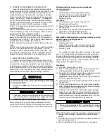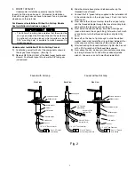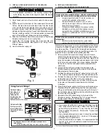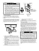
P. INSTALLATION TROUBLESHOOTING
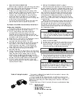
Problem: Leak at the drain saddle.
Possible Cause: Drain saddle not clamped tightly enough.
Solution: Tighten the drain saddle screws evenly and firmly.
Problem: Leak at the fittings threaded connection.
Possible Cause: Fitting is improperly taped or not `
tightened sufficiently.
Solution: Retape the threaded portion with PTFE tape and
thread it in firmly. Do not over tighten.
Problem: Leak at the fitting’s push-in connection.
Possible Cause: Tubing is damaged if there is a tubing mis-
assembly.
Solution: Remove the tubing. Squarely cut off 1/4 inch from
the end of the tubing using a sharp razor knife and reinsert it
into the fitting. Make sure that the tubing is pushed in com-
pletely until it seats.
Problem: Leak at the filter cartridge head.
Possible Cause: Damaged or misaligned O-ring.
Solution: Close the cold water supply shut off valve and the
storage tank valve. Lift up on the faucet handle and drain the
tank a minimum of 5 minutes. Remove the filter cartridge and
check the condition of the O-rings. If they are misaligned,
reseal them. If they are damaged, replace them.
Problem: The faucet leaks from the spout with the handle down.
Possible Cause: An obstructed or damaged valve seat in the
faucet mechanism.
Solution: Remove the faucet spout with a twisting/lifting
motion and slide the faucet handle forward over the spout
hole to gain access to the faucet valve. Unscrew the tee-bar
and the slotted bushing to remove the valve. Clean out any
obstruction or replace it with a new valve mechanism if neces-
sary.
Problem: No steady drip from the open faucet after the
tank is drained.
Possible Causes:
•
The cold water supply shut off valve is not open.
•
A leak from any product water fitting connection.
•
The icemaker valve was left open before the start-up
procedure completed.
•
Air is still trapped in the system.
Solutions:
•
Open the cold water supply shut off valve completely.
•
Correct the fitting leak as outlined above.
•
Close the icemaker valve and wait until the faucet drips.
•
Wait for the air to be purged from the system.
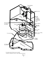
Problem: Water leaks from air gap module opening.
Possible Causes:
•
The drain line tubing is looped, kinked, or has a low spot.
•
The drain line is blocked or the drain hole is not drilled
through completely.
•
Air is locked in the air gap outlet.
•
There is excessive RO reject flow.
Solutions:
•
Trim any excess tubing to obtain a short, “straight-shot” to
the drain.
•
Check to see that the drain line is clear of any obstruction
and remove the drain saddle fitting to verify that the hole is
drilled through completely.
•
Blow air into the air gap outlet using a short length of tubing.
•
Disconnect the red SFC reject tubing from the faucet air
gap inlet tubing and check the reject flow rate. It should
be less than 5.9 ounces/min. If it is greater than 5.9 ounc
es/min, replace the red SFC reject tubing with the new one
of proper length.
Problem: Too little or no reject flow.
Possible Causes:
•
Red SFC reject tubing is plugged or damaged.
•
An obstruction in the faucet air gap module.
Solutions:
•
Replace the SFC reject tubing with one of proper length.
•
Remove the air gap module and inspect the internal flow
path. Replace the air gap module if necessary.
Problem: Chlorine or other unpleasant taste/odor is evi-
dent after the initial tank filling.
Possible Cause: Residual preservative/sanitizer is still in the
water.
Solution: Drain and fill the storage tank several times if
necessary.
Problem: Noise in the drain (gurgling or
dribbling sound).
Possible Cause: The reject water is dripping into the standing
water in the drain trap.
Solutions:
•
Make sure that the 3/8” black drain tubing from the faucet
air gap module slopes continuously downward to the drain
saddle without any loops or low spots.
•
Angle the drain piping so that the reject water runs down
the side of the drain pipe.
•
Change the location of the drain saddle to the horizontal
drain pipe or any alternate vertical drain pipe which is
farther from the trap. Properly plug the original hole.
•
Drill larger hole in drain pipe.
Caution: Make sure the drain saddle is always installed
above (before) the trap.
12


