SteamerGard™ Models WT -200 and WT -400
INSTALLATION SPECIFICATIONS
IMPORTANT NOTE:
The
SteamerGard™
system is designed to provide purified water for use in the
steam generator (boiler) of the steamer
only.
A separate tap water supply line is required for the
condenser system of the steamer. It is the responsibility of the steamer owner or the installer to provide
two separate water connections; one for purified water to the steam generator and a separate one for tap
water to the condenser system.
SteamerGard™ Components:
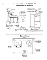
THE STEAMERGARD™ UNIT
is the heart of the system. It converts available tap water into chemically adjusted and
purified water using a combination of modem water treatment technologies. The
SteamerGard™
unit is designed to set
on the floor or a sturdy shelf (100 Ib. cap min.). The
SteamerGard™
unit should be positioned to provide easy access
for future fitter changes and servicing, along with access to a cold water supply (preferably softened), an open drain, and
a 115 VAC electrical outlet. The
SteamerGard™
unit is equipped with one 1/2" compression fitting to connect to the
feed water supply and two 3/8" compression fittings to connect to the drain and storage tank. 1/2'' and 3/8"-OD
polybutylene tubing is recommended for plumbing. The
SteamerGard™
unit plugs into a standard 115 VAC electrical
outlet.
THE STORAGE TANK
is a self-contained unit, and requires no power. It provides storage and pressure of purified
water for use in the steamer. The storage tank should be set on the floor anywhere between the
SteamerGard™
unit and
the steamer- The storage tank is fitted with a 1" shut-off valve and a 3/8" tee, tor connection to the
SteamerGard™
unit
and the steamer. 3/8" OD polybutylene tubing is recommended for plumbing.
Important.
Storage tank air precharge
should be 12 psi with no water.
THE CONTROL PANEL
is designed to give the operator important information about the status and performance of
the
SteamerGard™
system, as well as to provide a manual system bypass to revert the steamer to tap water operation
should overuse or failure cause the storage tank to become depleted. The control panel is designed to be wall mounted in
a convenient and accessible location in the vicinity of the steamer and with access to a cold tap water supply. It uses a
standard 9 volt battery to power the WATER QUALITY MONITOR , so no special wiring is required. It is equipped
with three 3/8" compression fittings for connection to the storage tank- the steam generator and a tap water supply.
3/8"OD polybutylene tubing is recommended for plumbing.
Plumbing
The
SteamerGard™
system is designed for operation with cold water (40°F - 80°F), at pressures of 25-80 psi,
containing less than 1500 ppm (mg/l) of TDS.
The SteamerGard™
system is designed to be plumbed with 3/8" and
1/2" OD polybutylene tubing. 3/8" and 1/2" plastic ferrules (sleeves) are supplied with the system and must be used
when plumbing polybutylene tubing to brass compression fittings. (Note: The tapered end of the plastic ferrule fits into
the fitting body.) if copper tubing must be used for the feed water supply lines, be sure to use
brass
ferrules (sleeves).
All manual water valves used in the
SteamerGard™
system are open when the handle is parallel to the valve body, and
are closed when the handle is perpendicular to the valve body- 3/8" OD and 1/2" OD polybutylene installation tubing is
available from The Water Factory.
Electrical
A 115 VAC electrical outlet is required as a power source for the
SteamerGard™
unit. A standard 9 volt battery,
located behind the remotely mounted control panel, is used to power the Water Quality Monitor.
1

