WaterFurnace works continually to improve its products. As a result, the design and specifi cations of each product at the time of order may be changed without notice. Please contact WaterFurnace at 1-888-929-2837 for latest design and
specifi cations. Purchaser’s approval of this data set signifi es that the equipment is acceptable under the provisions of the job specifi cation. Statements and other information contained herein are not express warranties and do not form the
basis of any bargain between the parties, but are merely WaterFurnace’s opinion or commendation of its products. The latest version of this document is available at www.waterfurnace.com.
Contractor: P.O.:
Engineer:
Project Name:
Unit Tag:
SD2552WNB 09/16
25
Page _____ of _____
ENVISION
2
NKW
REVERSIBLE CHILLER - 50Hz
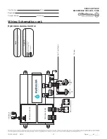
Wiring Schematics cont.
Reversible Chiller HydroLink Aurora 150 Series
CC2
EH1
Fa
ct
ory
Fault
AL
G
AL
M
LS
ES
AC
C c
Status
AURORA BASE
CONTROL™
RV – K1
CC
2
CC – K2
CC Hi – K3
Fan – K4
Alarm – K5
Acc – K6
AC
C n
o
AC
C n
c
O/
B
C
R
LO
G
Y1
Y2
W
DH
3A
-F
us
e
O/
B
C
R
LO
G
Y1
Y2
W
DH
LO
G
HI
CCG
CC
FG
F
R
HP
HP
LP
FP2
FP2
FP1
REV
REV
CF
M
PW
M
ECM PWM
Fa
ct
ory
Factory Fan Connection
R
R
CC
C
RS
4
85
EH2
C
EH1
C
CO
(+)
(-)
R
C
RS
485 E
xp
Fa
ct
ory
Com1
Com2
Config
G
G
G
Y
R
SW1 Test
FP1 – 15
o
F/30
o
F
JW2 - Alarm
P11
P5
P2
P1
P8
P7
P9
P6
P3
SW2
P13
P4
FP2 – 15
o
F/30
o
F
RV – B/O
ACC – Dip 4
ACC – Dip 5
CC – Dual/Single
L – Pulse/Continuous
NA/Normal
Fa
ct
ory U
se
Field Connections
Field Connections
C
LP
FP1
F
CC
G
Y1
1
2
3
4
5
6
7
8
Off
On
N/A
RS
485 NE
T
Notes
1 – Reversing Valve will be energized for heating mode.
2 – In Emergency Shutdown, line voltage is still present in control box. Emergency
Switch is wired on low voltage circuit only.
3 – See additional schematic for HydroLink details.
Current Transducer (CT)
Thermistor
Light emitting diode - Green
Relay coil
Capacitor w/ bleed resistor
Switch - Condensate overflow
Switch - High pressure
Switch - Low pressure
Polarized connector
Factory Low voltage wiring
Factory Line voltage wiring
Field low voltage wiring
Field line voltage wiring
Optional block
DC Voltage PCB traces
Junction
Quick connect terminal
Wire nut
Field wire lug
Ground
Fuse
Legend
Relay Contacts-
N.O., N.C.
G
T
1
3
2
P
L1
Breaker
CC –
Compressor Contactor
FP1 –
Freeze Protection
FP2 –
Freeze Protection
HP1, HP2 – High Pressure Switch
LP1, LP2 –
Low Pressure Switch
PB1 –
Power Block
RV1, RV2 – Reversing Valve Coil
SW1 –
TEST MODE ABC Board
SW2 –
DIP Package 8 Position ABC Board
CFM
P13
P4
SW1
P5
JW
2
P9
LO
O/B
Y2
W
DH
P8
P7
RS485 NET
RS485 NET
P6
RS485 EXP
P3
SW2
On
Future Use
L Output Type
CC – Dual/Single
Acc – Dip 5
Acc – Dip 4
RV – B/O
FP2 – 15
°F/30°F
FP1 – 15
°F/30°F
Com1
LED5
Com2
LED5
Test Mode
F1-3A
P1/P9
C
PWM
1
2
3
4
5
6
7
8
ALM
ALG
ACC COM
ACC NO
ACC NC
R
C
G
Y1
EH2
C
EH1
C
CO
C R
-
+
C R
-
+
Off
Fault
LED1
R
Status
LED3
Config
LED2
CC2
CC
F
C
R
F FG CC CCGCC2
HI
CC2
LO
CC2
G
REVREV FP1 FP1 FP2 FP2 LPS LPSHPSHPS
Aurora Base Control A
(ABC-A)
K1-
RV
Rel
ay
K2-
CC Re
lay
K3
-C
C2 R
ela
y
K4
-Fan R
ela
y
K5-Alarm
Relay
K6-Acc
Relay
F
R
C
CC
G
Y1
C
R
ES
LS
P2
EH1
Y
G
G
G
CFM
P13
P4
SW1
P5
JW
2
P9
LO
O/B
Y2
W
DH
P8
P7
RS485 NET
RS485 NET
P6
RS485 EXP
P3
SW2
On
Future Use
L Output Type
CC – Dual/Single
Acc – Dip 5
Acc – Dip 4
RV – B/O
FP2 – 15
°F/30°F
FP1 – 15
°F/30°F
Com1
LED5
Com2
LED5
Test Mode
F1-3A
C
PWM
1
2
3
4
5
6
7
8
ALM
ALG
ACC COM
ACC NO
ACC NC
R
C
G
Y1
EH2
C
EH1
C
CO
C R
-
+
C R
-
+
Off
Fault
LED1
R
Status
LED3
Config
LED2
CC2
CC
F
C
R
F FG CC CCGCC2
HI
CC2
LO
CC2
G
REVREVFP1 FP1 FP2 FP2 LPS LPSHPSHPS
Aurora Base Control B
(ABC-B)
K1
-R
V R
ela
y
K2
-C
C R
ela
y
K3-
CC
2 Re
lay
K4-
Fan R
ela
y
K5-Alarm
Relay
K6-Acc
Relay
F
R
C
CC
G
Y1
C
R
ES
LS
P2
EH1
Y
G
G
G
HP1
LP1
FP1-A
EX
-1
1
EX
-1
2
EX
-1
3
EX
-1
4
EX
-1
5
EX
-1
6
EX
-1
7
EX
-1
8
EX
-1
9
EX
-2
0
EX
-1
EX
-2
EX
-3
EX
-4
EX
-7
EX
-8
EX
-9
EX
-1
0
RV1
HP2
LP2
FP1-B
RV2
“EX”
Connector
(twist lock)
1
2
3
4
5
6
9
10
11
12
15
16
17
18
19
20
(Note 1)
P1/P9
(Note 1)
EX
-5
EX
-6
CC-A
CC-B
To AXB-B
To AXB-A
FP2-A
FP2-B
7
8
13
14
Or
ange (
1)
Bl
ue
(8
)
Bl
ue
(7
)
Bl
ac
k (
10
)
Ye
llo
w (
3)
Ye
llo
w (
4)
Or
ange (
2)
Gr
ay
(5
)
Gr
ay
(6
)
Bl
ac
k (
9)
Or
ange
/W
hit
e (
11
)
Bl
ue/
W
hit
e (
18
)
Bl
ue/
W
hit
e (
17
)
Bl
ac
k/W
hit
e (
20
)
Ye
llow
/W
hit
e (
13
)
Ye
llo
w
/W
hit
e (
14
)
Or
ange
/W
hit
e (
12
)
Gr
ay
/W
hit
e (
15
)
Gr
ay
/W
hit
e (
16
)
Bl
ac
k/W
hit
e (
19
)
PGM
11
10
Violet (60)
Black/White (61)
PGM
Black (59)
Black (68)
9
8
Red (71)
CPM2
M2
M1
Violet/White (62)
Black/White
(69)
Black/Orange
72B
Black/Orange
(71B)
CPM1
M2
M1
Black 72A
Black
(71A)
Aquastat
Commands


