WATERMAZE SERIES
OPERATOR’S MANUAL
23
WB • 8.913-984.0-L
A
D
B
C
Bucket
(Not Included)
E
F
4. On/Off/ Full Speed Switch
Now that the system is adjusted, turn the pump on.
The pump will come on and inject “anti-foam” into the
waste stream when the wastewater pump comes on.
The Full Speed setting can be used to fill the feed
lines more quickly.
Sludge Removal:
Remove the doors on the right side of the
WATER MAZE
.
At the bottom of the evaporation tank you will find a
1-1/2" ball valve. Connect a hose to the valve and place
the other end into a container. Open the valve and flush
out the sludge. If nothing comes out, you may need to
run a wire into the valve to break loose the sludge that
has collected in the evaporation tank. Once the sludge
has been drained, close the valve.
NOTE: Drain water level below the sparger tube before
removing item
E (See figure on page 23).
Sparger Tube Cleaning:
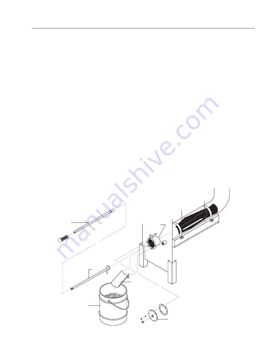
The tool kit, (8.903-719.0), consists of four items. Check
to ensure that the kit is complete (refer to the drawing).
A. Tool handle (2 pc.)
B. Probe/scraper
C. Trough assembly
Remove the panel that covers the flange assembly (this
cover is not shown in this drawing). Use a 3/4" socket to
remove the nuts holding the front of the flange assembly
(
E) from the rear flange assembly (D). Also remove the
gasket and check it for damage or wear.
Next, place the trough assembly (
C) onto the bottom
two studs of the rear flange (
D) and replace the nuts to
hold it securely in place. Assemble the tool by screwing
the tool handle (A) into the probe/scraper (
B). Place the
probe/ scraper tool as far back into the sparger tube as
possible. While pulling the scraper forward, scrape out all
of the buildup that has accumulated inside of the sparger
tube (
H) and direct it into the slot of the sparger tube.
Continue until the sparger is clean. Clean out the slot (
F)
inside the sparger tube. Remove sludge from the bottom
of the tank monthly.
Once this is completed, remove the probe/scraper and
the trough assembly (
C). Make sure the gasket is clean
along with the surface area between the front flange (
E)
and the rear flange assembly (
D). Place the gasket over
the studs on the rear flange assembly and then do the
same with the front flange assembly (
E). Use the 1/2"
nuts to secure the flange assembly. Refill the evaporator
tank and check the flange assembly for leaks. Replace
the panel that covers the flange assembly.
Figure 9
H


