background image

6

7

 INSTALLING  GROUND:

 To maintain an electrical ground in metal plumbing of a home’s cold water piping 

(such as a copper plumbing system), install a ground clamp or jumper wiring. 

NOTE: If replacing an existing unit, also replace the ground clamps/wire. If removing a unit, replace the 

piping with the same type of piping as the original to assure plumbing integrity and grounding. 

9.


DRAIN LINE:

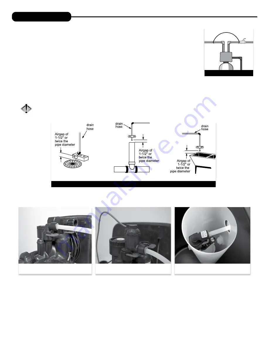
 First, be sure that the drain can handle the backwash rate of the system. Solder joints near the 

drain must be done prior to connecting the drain line flow control fitting. Leave at least 6” between the drain 

line flow control fitting and solder joints. Failure to do this could cause interior damage to the flow control. 

Install a 1/2” I.D. tube to the Drain Line Assembly in accordance with plumbing regulations or discard the tubing 

nut and use the 3/4” NPT fitting for rigid pipe (recommended). If the backwash rate is greater than 7 gpm, use a 

3/4” drain line. Where the drain line is elevated but empties into a drain below the level of the control valve, form 

a 7” loop at the discharge end of the line so that the bottom of the loop is level with the drain connection on the control valve. This will provide 

an adequate anti-siphon trap. Piping the drain line overhead <10 ft is normally not a problem. Be sure adequate pressure is available (40-60 psi is 

recommended). Where the drain empties into an overhead sewer line, a sink-type trap must be used with appropriate air gap (see drawing). Run 

drain tube to its discharge point in accordance with plumbing codes. Pay special attention to codes for air gaps and anti-siphon devices.

CAUTION:  Never insert a drain line into a drain, sewer line, or trap. Always allow an air gap of 1-1/2” or twice the pipe 

diameter, whichever is greater, between the drain line and the wastewater to prevent the possibility of sewage 

being back-siphoned into the softener.

SHUTOFF

VALVE

GROUND

STRAP

TYPICAL DRAIN LINE INSTALLATIONS

GROUND STRAP

INSTALLATION

1. Floor Drain

2. Standpipe

3. Laundry Tub

10.   

SAFETY BRINE TANK CONNECTION:

 Install the 3/8” O.D. polyethylene tube from the Refill Elbow to the Brine Safety Float valve in the 

brine tank.

11.  

OVERFLOW LINE CONNECTION:

 An overflow drain line is recommended where a brine overflow could damage furnishings or the building 

structure. Your unit is equipped with a brine tank safety float which greatly reduces the chance of an accidental brine overflow. In the event of 

a malfunction, however, an overflow line connection will direct the “overflow” to the drain instead of spilling on the floor where it could cause 

considerable damage. This fitting is an elbow on the side of the brine tank. Attach a length of 1/2” I.D. tubing to fitting and run to drain. Do not 

elevate overflow line higher than 3” below bottom of overflow fitting. Do not connect this tube into the drain line of the control valve. Overflow 

line must be a direct, separate line from overflow fitting to drain, sewer, or tub. Allow an air gap as per the drain line instructions.

Connection at Refill Elbow on the control valve

Connection at Brine Safety Float in brine tank

Connection at Refill Elbow on the control valve 

(with optional chlorine generator)

Summary of Contents for ASP1-1044

Page 1: ...Installation Instructions Owner s Manual Sanitizer Plus Series Water Conditioners For Models ASP1 1044 ASP1 1054 ASP1 1354 ASP2 1044 ASP2 1054 ASP2 1354 ...

Page 2: ...refully and understand the cautions and notes before installing This manual should be kept for future reference If you have any questions regarding your water conditioner contact your local dealer YOUR WATER TEST Hardness_______________________ gpg Iron___________________________ ppm pH____________________________ number Nitrates_______________________ ppm Manganese_____________________ ppm Sulphu...

Page 3: ...e time of day and gallons per minute Flow rate vacation mode capacity remaining and days to a regeneration are optional displays For more explanation consult the operating displays and maintenance section Pressing the NEXT button on a general operating screen will cycle through the available operating displays In any screen other than a general operating display the NEXT button will proceed to the...

Page 4: ...les point in the direction of flow indicated by the engraved arrows on the control valve Water flows through the control valve for normal operation of a water softener or filter During the regeneration cycle this position provides regeneration water to the unit while also providing untreated water to the distribution system Fig 1 2 BYPASS POSITION The inlet and outlet handles point to the center o...

Page 5: ...nds the use of an expansion tank on the outlet side of the unit see diagram 5 Do not locate unit where it or its connections including the drain and overflow lines will ever be subjected to temperatures under 33 F 6 Do not subject the tank to any vacuum as this may cause an implosion and could result in leaking If there is a possibility a vacuum could occur please make provision for a vacuum break...

Page 6: ... Run drain tube to its discharge point in accordance with plumbing codes Pay special attention to codes for air gaps and anti siphon devices CAUTION Never insert a drain line into a drain sewer line or trap Always allow an air gap of 1 1 2 or twice the pipe diameter whichever is greater between the drain line and the wastewater to prevent the possibility of sewage being back siphoned into the soft...

Page 7: ...7 This page intentionally left blank ...

Page 8: ...ncy of regeneration and will not alter or affect the hardness of the water treated by the unit Note If a resin media is used increase the grains per gallon if soluble iron is present 1 ppm 4 gpg This screen will not display if FILTER mode is selected STEP 3 DAYS BETWEEN REGENERATION DAY OVERRIDE Use the or buttons to adjust the day override Adjustable from 1 28 days or OFF The manufacturer has fac...

Page 9: ...nlet handle of the bypass valve very slightly allowing water to fill the tank slowly in order to expel air CAUTION If water flows too rapidly there will be a loss of media to the drain 3 When the water is flowing steadily to the drain without the presence of air slowly open the inlet valve Restore power and momentarily press the button to advance the control to the BRINE position 4 With the bypass...

Page 10: ...water use is anticipated or when the system has been operating without salt To initiate a manual regeneration at the next preset regeneration time press and release the REGEN button The words REGEN TODAY will flash on the display to indicate that the system will regenerate at the scheduled regeneration time see the Programming Procedures section If you pressed the REGEN button in error pressing an...

Page 11: ... control valve was not able to function properly 6 BRINE TANK MAINTENANCE AND SALT Refill the brine tank as necessary making sure at least 1 3 of the brine tank is full at all times Without proper salt levels the water softener may not operate properly Because typical settings of this water softener include a dry salt storage feature a small amount of water in brine tank between regeneration the m...

Page 12: ...d B Connect meter to three pin connection labeled METER on PC board C Restricted stalled meter turbine C Remove meter and check for rotation or foreign material D Meter wire not installed securely into three pin connector D Verify meter cable wires are installed securely into three pin connector labeled METER E Defective meter E Replace meter F Defective PC board F Replace PC board 4 Control valve...

Page 13: ...amming Check refill flow control for restrictions or debris and if necessary replace H Damaged seal stack assembly piston H Replace seal stack assembly and or piston I Control valve body type and piston type mix matched I Verify proper control valve body type and piston type match J Fouled media bed J Replace media bed 9 Control valve uses too much regenerant A Improper refill setting A Check refi...

Page 14: ...on the PC board labeled MOTOR Press NEXT and REGEN buttons for 3 seconds to resynchronize software with piston position or disconnect power supply from PC board for 5 seconds and then reconnect B PC board not properly snapped into drive bracket B Properly snap PC board into drive bracket and then Press NEXT and REGEN buttons for 3 seconds to resynchronize software with piston position or disconnec...

Page 15: ...AV NHBP motor to PC board two pin connection labeled DRIVE Press NEXT and REGEN buttons for 3 seconds to resynchronize software with piston position or disconnect power supply from PC board for 5 seconds and then reconnect C MAV NHBP motor not fully engaged with reduction gears C Properly insert motor into casing do not force into casing Press NEXT and REGEN buttons for 3 seconds to resynchronize ...

Page 16: ...tory screens These do not flash when error occurs A Occurs when dP input is active for ALARM and the input is closed The alarm buzzer will activate and the screen will display the error A Check for low flow leak Press NEXT and REGEN buttons for 3 seconds to resynchronize software with piston position or disconnect power supply from PC Board for 5 seconds and then reconnect to clear error 24 Err 40...

Page 17: ...Qty 1 CV3540S A Black Sanitizer cover 1 CV3540S W A Gray Sanitizer cover 1 2 CV3107 1 Motor 1 3 CV3002A Drive assembly includes 5 and 6 4 CV3554WS 03 PC board Sanitizer 1 5 CV3110 Drive gear 12 x 36 3 6 CV3109 Drive gear cover 1 Not Shown CV3526 Transformer 110V 12V 1 Not Shown CV3543 Optional weather cover 1 ...

Page 18: ...1 CV3011 01 1 piston assembly upflow 1 CV3407 1 25 piston assembly downflow 1 5 CV3174 Regenerant piston 1 6 12 CV3015A WS1 QC2 Tank adapter assembly includes O rings 1 13 CV3001 04 1 body assembly downflow 1 CV3001 04UP 1 body assembly upflow 1 CV3001 1 body assembly downflow 1 CV3001UP 1 body assembly upflow 1 CV3020 1 25 body assembly downflow 1 14 CV3541 Drive backplate 1 Not Shown CD1225 05 T...

Page 19: ... 5 CV3395 Chlorine Generator Black 1 CV3395 G SaltMonitor Gray 1 BYPASS VALVE Item No Part No Description Qty 1 CV3006 Bypass assembly 1 2 CV3147 Bypass handles 2 Loosens Injector And Bypass Caps Loosens Drive Cap Although no tools are necessary to assemble or disassemble the valve the Service Wrench shown in various positions on the valve is available to aid in assembly or disassembly SERVICE WRE...

Page 20: ... assembly CV3010 1F F injector assembly CV3010 1G G injector assembly CV3010 1H H injector assembly CV3010 1I I injector assembly CV3010 1J J injector assembly CV3010 1K K injector assembly not shown CV3170 O ring 011 lower not shown CV3171 O ring 013 upper The injector plug and the injector each use one lower and one upper o ring REPLACEMENT PARTS 3 WATER METER AND METER PLUG Item No Part No Desc...

Page 21: ...in 1 Strt No Sil 1 REPLACEMENT PARTS Water flow Proper DLFC orientation directs water flow towards the washer face with rounded edge DRAIN LINE ASSEMBLY 3 4 Item No Part No Description Qty 1 CH4615 Elbow locking clip 1 2 CPKP10TS8 BULK Optional insert 5 8 tube 1 3 CV3192 Optional nut 3 4 drain elbow 1 4 CV3158 02 Drain elbow 3 4 NPT with O ring 1 5 CV3163 O ring 019 1 6 CV3159 01 DLFC retainer ass...

Page 22: ...1 4 CH1030 29S 4 x 29 slotted brine well 18 x 33 BT 1 CH1030 36S 4 x 36 slotted brine well 18 x 40 24 x 40 BT s 1 5 CH1018 2 piece overflow set 1 6 CH4500 48 474 air check assembly 1 2 x 48 1 7 CH4620 474 float assembly 7 1 8 CH4600 50 474 safety brine valve w 5 gpm glow control 1 9 CH7016 Cap 4 brine well 1 10 CH4626 Nut safety brine valve stand off 1 Assemblies 11 CH4700 29WR 1 5 gpm safety floa...

Page 23: ...ay with 474 Brine Assembly 1 Not shown CH4850 34 625 Brine Well with Brine Well 474 Assembly 34 5 8 1 LOW PROFILE CABINET AND BRINE TANK Item No Part No Description Qty 1 CJ2TCWSLP C Top Assembly Black 1 2 CJ2B35E Bottom Assembly Light Gray with 474 Brine Assembly 1 Not shown CH4850 34 625 Brine Well with Brine Well 474 Assembly 34 5 8 1 2 1 REPLACEMENT PARTS ...

Page 24: ...t No Description Qty CV3007 07 1 1 4 1 1 2 PVC solvent assembly 2 4 CV3352 Fitting 2 3 4 BRASS SHARK BITE Item Part No Description Qty CV3007 12 3 4 brass shark bite assembly 2 4 CV3628 Fitting 2 1 PLASTIC MALE NPT Item Part No Description Qty CV3007 04 1 plastic male NPT assembly 2 4 CV3164 Fitting 2 1 1 4 PLASTIC MALE NPT Item Part No Description Qty CV3007 05 1 1 4 plastic male assembly 2 4 CV3...

Page 25: ...00 12 4 22 600 15 9 36 900 21 2 20 300 12 4 34 800 15 9 60 300 26 5 Amount of Media Cu Ft 1 0 1 5 2 5 1 0 1 5 2 5 Maximum Water Hardness GPG 20 30 40 40 60 80 2 Maximum Iron and Manganese PPM 8 0 10 0 15 0 8 0 10 0 15 0 3 Minimum pH 6 5 6 0 6 0 7 0 7 0 7 0 4 Total pH Adjusted Water 510 510 863 N A N A N A 5 Peak Flow Rate GPM P PSI 19 0 8 3 17 0 7 8 19 0 7 6 19 0 9 3 17 0 9 1 19 0 8 6 Con nuous Fl...

Page 26: ...he part or component at its expense and return part freight collect The above provisions of the warranty are valid as long as the unit is connected in compliance with local plumbing codes and in an equivalent manner and condition of the original installation and is owned by the original owner This warranty does not cover damages due to accident fire flood freezing or any other Act of God We are no...

Page 27: ...r to make adjustments please complete the following steps QUICK REFERENCE GUIDE GENERAL OPERATION When the system is operating one of five displays will be shown time of day gpm flow rate capacity remaining or days to a regen Pressing will toggle between the five choices TO SET TIME OF DAY In the event of a prolonged power outage time of day flashes indicating that this needs to be reset All other...

Page 28: ... 2021 Water Right Inc All rights reserved MAN SAN PLUS RevA0821 1900 Prospect Court Appleton WI 54914 Phone 920 739 9401 Fax 920 739 9406 ...

Reviews: