-2-
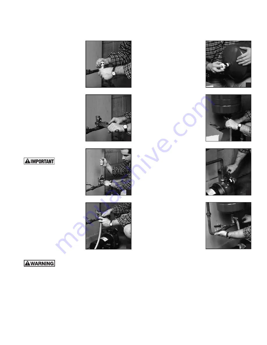
6. Put together pipe tee assembly.
a. Wrap Teflon
®
tape around the
male threads on both ends of the
close nipple. Apply clockwise (i.e.
bottom up and coming towards
you). Or apply pipe sealant.
b. Install the close nipple into the
pipe tee. Tighten hand tight.
(Fig. 4)
c. Install the other end of the close
nipple by inserting it into the
female threaded opening in the
supply line from the pump, where
the old tank was installed. (The
close nipple now has the pipe tee
pointing straight up.) Tighten the
tee using a pipe wrench 3-4 turns
after hand tight.
Point the opening on the side
of the tee to the front or to the
side so that it is easily accessible.
(Fig. 5)
7. Check to see whether you have
a pressure relief valve installed
somewhere between the pump
and the tank. If you do, then skip
this step.
Always
be
sure to equip
your well system with a proper
pressure relief valve.
If you do not yet have one in
the system between your pump
and tank: Install the pressure
relief valve in the straight pipe
tee. Wrap Teflon
®
tape around
the male threads. Or apply pipe
sealant. Insert the male end
into the other female threaded
opening on the pipe tee. Tighten
hand tight. Tighten wrench tight
using the adjustable wrench.
(Fig. 6)
8. Attach a pipe or hose to steer any
emergency overflow water away
from the electrical connections
of the pump if necessary.
Do not
install a plug or valve or insert
anything else in the pressure
relief valve that would obstruct
the flow of water from it. This
can create a serious safety
hazard in your home.
A drip pan connected to an adequate drain
must be installed if leaking and flooding
could cause property damage to the area adjacent to the
appliance or to lower floors of the structure.
If the pressure relief valve is located above something that
could be damaged by spilled water, then attach a pipe or hose
to the valve to redirect any emergency discharge.
(Fig. 7)
Cut a 1/2” plastic hose to a length long enough to steer water
clear of whatever you don’t want to get wet. Insert one end
of the plastic hose over the end of the 1/2” plastic hose barb.
Screw the barb hose assembly
into the pressure relief valve.
Tighten wrench tight with the
adjustable wrench.
9. Install the new tank.
a. Wrap Teflon
®
tape around the
threads of the male connection
on the tank or apply pipe sealant.
(Fig. 8)
b. Install the new tank in the
female threaded opening of
the pipe tee. Turn hand tight.
Tighten wrench tight using the
12” adjustable wrench on the
hex connection at the bottom of
the tank.
(Fig. 9)
c. Remove the plastic cap on the
air valve on top of the tank.
Check the air charge in the tank
using the tire pressure gauge.
Adjust the pre-charge pressure
in the tank to be 1 to 2 psi
below the pressure switch pump
cut-in setting. First, look inside
the cap to the pressure switch
to determine the pump cut-in
setting. It should say “20/40” or
“30/50” or the like. The pressure
in the tank should be adjusted
to be 2 psi below the lower of
these two numbers. That is, the
tank pressure should be set at
about 18 psi if the cap indicates
a setting of 20/40, or set at
about 28 if the cap indicates a
setting of 30/50.
Models HT2B, HT4B and HT8B
are pre-charged with 38 psi
when shipped from the factory.
If this charge is too high, release
some air by pressing down on
the pin inside the air valve. If the
charge is too low, pump it up
using a bicycle tire pump.
Alternatively, you can adjust
the pressure switch to match
the pressure in the tank. See
instructions on the inside of the
cap to the pressure switch for
how to do this.
10. Open the ball or gate valve on the
pump feed line (that you closed
in Step 4).
(Fig. 10)
This will allow the pump to draw water
from the well into the house.
Open the ball or gate valve on the supply line (that you
closed in Step 2).
(Fig. 11)
This will allow the well system to
pump water into the plumbing in your house.
Shut off the faucet upstairs!
11. Turn on the power.
12. Look for leaks. If there are any, shut the power off. Tighten
or redo the leaky connections.
4
8
9
10
11
5
6
7


