WATERAX
STRIKER-2/3 Owner's Manual
09/2015
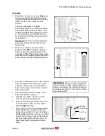
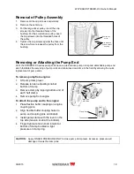
21
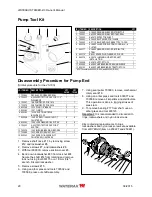
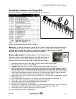
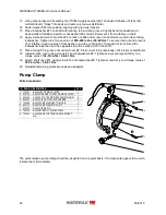
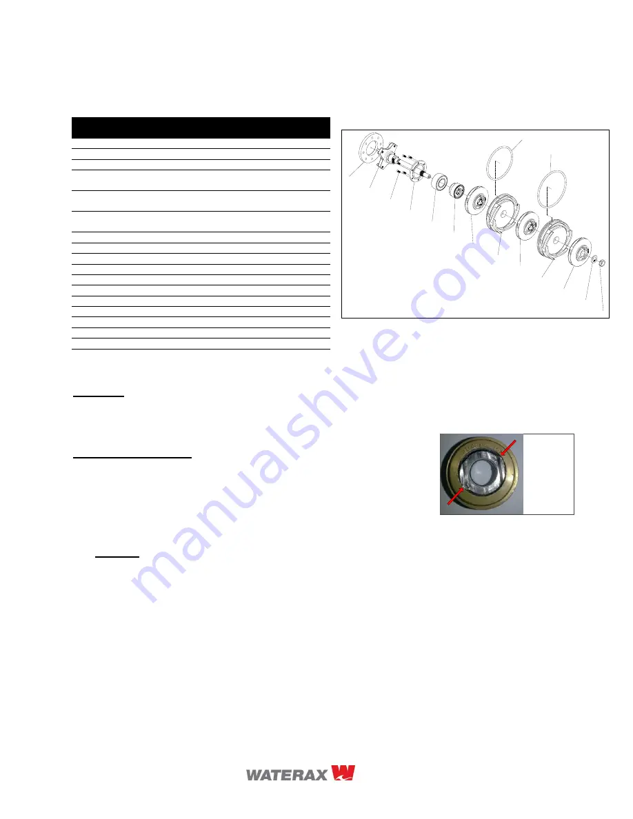
Assembly Procedure for Pump End
(Similar procedure for the 25-16S, will have fewer impeller and distributor)
13
14
15
16
17
18
19
20
25
21
22
23
24
26
19
(2/2)
Important:
When reusing components, carefully inspect the parts. Ensure that key dimensions are within
acceptable limits. Visually inspect the parts for pitting, worn vanes, damaged threads, damaged gasket
faces, excessive corrosion, deformation, etc. Discard any component that is not within acceptable
standards. Ensure that the components are clean before installing.
Mechanical Rotary Seal:
The mechanical rotary seal requires careful
inspection. The seal should be discarded if there are signs of leaks or if the
internal drive bushing is excessively deformed. The drive bushing must be
free to rotate without contact with the brass housing. If there is contact
between the drive bushing and the housing, the seal must be discarded.
1. Slide bearing retaining ring #16 on shaft #14 with plain face toward coupling collar.
2. Press bearing #17 on shaft using tool 600052.
3.
Carefully
press rotary seal #18 in pump body #3 using pressing sleeve tool 700531.
4. Apply a small amount of dish soap on mechanical rotary seal O-ring to facilitate installation of pump
shaft. Carefully pass end of shaft assembly through mechanical rotary seal bore. Make sure that flat
sections of shaft line up with rotary seal drive bushing flat sections. Gently press down shaft until ball
bearing rests firmly against shoulder in pump body. To verify that shaft has been properly installed,
slowly rotate shaft by hand; rotary seal drive bushing should rotate with shaft.
5. Attach retaining ring #16 to pump body with six screws #15 to a torque value of
22-25 in-lbs / 2.5-2.8
Nm
. Tighten evenly.
6. A small amount of marine grease can be applied onto shaft to facilitate future disassembly.
7. Slide impeller #19 onto shaft, and engage with mechanical rotary seal.
8. Smear the O-rings with a suitable lubricant to facilitate assembly.
9. Place O-ring #25 in groove of distributor #20.
10. With open end of pump body in vertical position, carefully lower distributor #20 until it rests on bottom
of body. Ensure that O-ring did not fall out of position during installation of distributor.
11. Slide impeller #19 into position, aligning with previous impeller.
12. Place O-ring #26 in groove of distributor #21.
ID ITEM NO DESCRIPTION
QTY
25-16S
QTY
18-16S
13 700006
12-17 COUPLING BUFFER
1
1
14 700042
18-2C PUMP SHAFT FOR 18-16
-
1
14 700066
25-2C PUMP SHAFT FOR 25-16
1
-
15 800364
12-25 SCREW #8-32X7/16 PHILLIPS
FLAT NYLON LOCK SS
6
6
16 700032
12-3 RETAINING RING FOR BEARING,
ALU.
1
1
17 700044
12-48S DOUBLE ROW BALL BEARING
WITH SEAL
1
1
18 700008
12-28NS MECHANICAL ROTARY SEAL
1
1
19 700036
12-7 IMPELLER, ALU.
1
2
20 700014
12-6 DISTRIBUTOR, ALU.
1
1
21 700065
12-9 DISTRIBUTOR, ALU.
-
1
22 700074
12-11 IMPELLER, ALU
1
1
23 600089
12-49 LOCKWASHER SS
1
1
24 700012
12-50 LOCK NUT SS
1
1
25 800450
12-26 O-RING
1
1
26 800363
12-27 O-RING
-
1
- 701169
GASKET BURASIL FOR 12-28NS SEAL
-
-
- 701170
O-RING FOR 12-28NS SEAL
-
-
NOTE:
The sealed bearing eliminates pump failure dangers related to improper
greasing by completely removing the need to grease the pump end bearing.
Drive bushing
shoulders in
contact with
seal housing;
seal must be
discarded.


