14
TRUCLIMATE 700 90-140 TON INSTALLATION MANUAL
Chiller Installation
1.
Unpack and inspect unit and pipe rack. Note and photograph any damage that is visible. Check for:
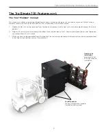
2. Using a forklift move the header rack into position.
3. Using a forklift rated appropriately for the unit’s weight, slide forks in fork pockets of the main unit. Once you have the
load on the forklift, angle the blades so they are tilted higher in the front and lower in the back. It is recommended to
carry the load a low as possible (maximum of 2 inches). NOTE: The placement of the compressor and heat exchangers
on this unit creates greater weight toward the rear.
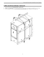
4. Once units are placed appropriately for installation, remove 4 victaulic connections (image below) and retain for later
installation.
Remove (4)
victaulic
connections
̆
panel damage
̆
pipe rack damage
̆
loose victaulic connections on header racks
(that will not be removed during installation)
̆
tight compressor bolts
̆
tight frame bolts
̆
secure headers
̆
wiring or component movement in control box
̆
damage during transportation
̆
oil inside the unit
Summary of Contents for TruClimate 700
Page 2: ......
Page 10: ...10 TRUCLIMATE 700 90 140 TON INSTALLATION MANUAL Dimensional Data...
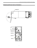
Page 11: ...11 TRUCLIMATE 700 90 140 TON INSTALLATION MANUAL Dimensional Data Service Clearance...
Page 12: ...12 TRUCLIMATE 700 90 140 TON INSTALLATION MANUAL Dimensional Data Center of Gravity...
Page 13: ...13 TRUCLIMATE 700 90 140 TON INSTALLATION MANUAL Dimensional Data Rigging Data...
Page 25: ...25 TRUCLIMATE 700 90 140 TON INSTALLATION MANUAL Wiring Schematic next page...
Page 36: ...36 TRUCLIMATE 700 90 140 TON INSTALLATION MANUAL Evaporator Pressure Drop...
Page 37: ...37 TRUCLIMATE 700 90 140 TON INSTALLATION MANUAL Condenser Pressure Drop...
Page 39: ...39 TRUCLIMATE 700 90 140 TON INSTALLATION MANUAL Screw Refrigeration Cycle Analysis...


