background image

29

TRUCLIMATE 700 90-140 TON INSTALLATION MANUAL 

HydroLink2 Aurora Chiller Controls cont.

Field Selectable Options via Hardware 

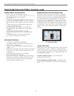
DIP Switch (SW1) – Test/Configuration Button (See SW1 
Operation Table) 

Test Mode 

The control is placed in the test mode by holding the push 
button switch SW1 for 2 - 5 seconds. In test mode most of 
the control timings will be shortened by a factor of sixteen 
(16). LED3 (green) will flash at 1 second on and 1 second off. 
Additionally, when entering test mode LED1 (red) will flash 
the last lockout one time. Test mode will automatically time 
out after 30 minutes. Test mode can be exited by press-
ing and holding the SW1 button for 2 to 5 seconds or by 
cycling the power. NOTE: Test mode will automatically be 
exited after 30 minutes. 

Reset Configuration Mode 

The control is placed in reset configuration mode by holding 
the push button switch SW1 for 50 to 60 seconds. This will 
reset all configuration settings and the EEPROM back to 
the factory default settings. LED3 (green) will turn off when 
entering reset configuration mode. Once LED3 (green) turns 
off, release SW1 and the control will reset. 

DIP Switch (SW2) 

SW2-1 FP1 Selection – Low water coil temperature limit setting 
for freeze detection. On = 30°F [-1.1 °C]; Off = 15°F [-9.4°C]. 
On is default.
SW2-2 FP2 Selection – On = 30°F [-1.1 °C]; Off = N/A. On is 
default.
SW2-3 RV – O/B - Reversing Valve Position. Normally cooling 
"B" or normally heating "O" On = O; Off = B. B is default.
SW2-4 and 2-5 Access Relay Operation (P2).  On and On is 
default.
SW2-6 CC Operation – selection of single or dual capacity 
compressor.  On = Single Stage; Off = Dual Capacity.  On is 
default.

SW2-7 Lockout and Alarm Outputs (P2) – selection of a 
continuous or pulsed output for both the LO and ALM 
Outputs. On = Continuous; Off = Pulsed.  On is default.
SW2-8 Future Use.  On is default.

Alarm Jumper Clip Selection

From the factory, ALM is connected to 24 VAC via JW2. By 
cutting JW2, ALM becomes a dry contact connected to ALG. 

Access Relay Operation

SW2-4

SW2-5

Cycles with Blower

ON

ON

Cycle with Compressor

OFF

OFF

Water Valve Slow Opening

ON

OFF

(Reserved)

OFF

ON

Software Features

Safety Features

The following safety features are provided to protect the 
compressor, heat exchangers, wiring and other components 
from damage caused by operation outside of design 
conditions. 

Fuse –

 a 3 amp automotive type plug-in fuse and each ABC 

provides protection against a low Voltage short circuit or 
overload conditions. 

Anti-Short Cycle Protection –

 5 minute anti-short cycle 

protection for the compressor. 

Compressor Minimum On Time - 

5 minute minimum on-time 

protection for the compressor to insure oil circulation for each 
compressor cycle.

Random Start – 

5 to 80 second random start upon power up 

and return from load shed or emergency shutdown. 

Fault Retry –

 in the fault condition, the control will stage off 

the outputs and then “try again” to satisfy the Y input call. 
Once the thermostat input calls are satisfied, the control will 
continue on as if no fault occurred. If 3 consecutive faults 
occur without satisfying the thermostat Y input call, then the 
control will go to lockout mode. 

Lockout – 

when locked out, the Alarm output (ALM) 

and Lockout output (L) will be turned on. The fault type 
identification display LED1 (Red) shall flash the fault code.  
Lockout may also be reset by turning power off for at least 30 
seconds or through HMI or BACnet.
 

High Pressure – 

The E2 fault is recognized when the Normally 

Closed High Pressure Switch, P4-9/10 opens, no matter how 
momentarily. The High Pressure Switch is electrically in series 
with the Compressor Contactor and serves as a hardwired 
limit switch if an overpressure condition should occur.

Low Pressure -

 The E3 fault is recognized when the Normally 

Closed Low Pressure Switch, P4-7/8 is continuously open for 
30 seconds. Closure of the LPS any time during the 30 second 
recognition time restarts the 30 second continuous open 
requirement. 

Loss of Charge -

 the E6 fault is recognized when the Normally 

Closed Low Pressure Switch, P4-7/8 is open prior to the 
compressor starting.

Summary of Contents for TruClimate 700

Page 1: ...entive Maintenance TruClimate 700 90 140 Ton Installation Manual I ll i M l Commercial 60 Hz Water Cooled Chiller R 513A Refrigerant 90 140 Ton Lead Variable Speed Compressor Installation Information...

Page 2: ......

Page 3: ...stance Transport 19 Water Quality 20 Water Connections 22 Operating Limits 22 Electrical Data 23 Electrical Connections 23 Electrical System and Controls Safety Circuit 24 Wiring Schematics 26 HydroLi...

Page 4: ...condition Examine units for shipping damage removing unit packaging if necessary to properly inspect unit Units in question should also be internally inspected If any damage is observed the carrier s...

Page 5: ...oltage 4 460 60 3 Electrical Option A Fused Disconnect Control Option D Primary Unit Master Controller Non Standard Options SSS None Future Option N Not Applicable Future Option 0 Not Applicable Futur...

Page 6: ...modules B 3 modules C 4 modules D 5 modules Family HSC HydroLink Supervisory Control Chiller Module N NXW Compact Scroll D WC Dual Scroll Modular Chiller S WCHVE VS Dual Screw Chiller Header Rack A No...

Page 7: ...d standard provisions for remote access using BACnet Color touch screen chiller interface provides easy to use instant access to unit performance Low impedance line reactors reduce harmonic noise and...

Page 8: ...speed drive integrated with compressor provides envelope control for improved reliability DC Inverted Variable Speed Single Screw Compressor Removable 4 pipe header rack Full enclosure foam lined pan...

Page 9: ...d WaterFurnace modular screw units feature several industry firsts to provide a true modular chiller 1 Modular chiller unit can be removed from the bank and replaced with a new unit using strategicall...

Page 10: ...10 TRUCLIMATE 700 90 140 TON INSTALLATION MANUAL Dimensional Data...

Page 11: ...11 TRUCLIMATE 700 90 140 TON INSTALLATION MANUAL Dimensional Data Service Clearance...

Page 12: ...12 TRUCLIMATE 700 90 140 TON INSTALLATION MANUAL Dimensional Data Center of Gravity...

Page 13: ...13 TRUCLIMATE 700 90 140 TON INSTALLATION MANUAL Dimensional Data Rigging Data...

Page 14: ...er in the back It is recommended to carry the load a low as possible maximum of 2 inches NOTE The placement of the compressor and heat exchangers on this unit creates greater weight toward the rear 4...

Page 15: ...INSTALLATION MANUAL Chiller Installation cont 5 Remove 4 u bolts image below and retain for later installation 6 Remove 4 pipes that are attached to the pipe rack in shipment image below Remove 4 U bo...

Page 16: ...victaulic connections that were previously removed 8 Using a forklift move main unit into position carefully guiding pipes from heat exchangers into the pipe rack 9 Once both unit and pipe rack are in...

Page 17: ...TRUCLIMATE 700 90 140 TON INSTALLATION MANUAL Chiller Installation cont 10 Install bolts along the junction of pipe rack frame and unit body 11 Attach the quick connect isolation valves and flow switc...

Page 18: ...e unit frame see image 2 Slightly lift 2in maximum the module and pull away from the bank Make sure the module sensors do not come into contact with any of the structural members of the header rack 3...

Page 19: ...sport 1 When lifting the chiller all lifting brackets must be used 2 Always use spreader bars The sound enclosure of the chiller may be damaged if spreader bars are not used 3 The front pockets of the...

Page 20: ...the basis of acceptable pressure drop and not on pipe diameter The strainers selected should have a pressure drop at the nominal ow rate of the units low enough to be within the pumping capacity of th...

Page 21: ...en egg smell appears at 0 5 ppm 10 50 ppm Less than 1 ppm Sulfates Less than 125 ppm Less than 125 ppm Less than 200 ppm Chlorine Less than 0 5 ppm Less than 0 5 ppm Less than 0 5 ppm Chlorides Less t...

Page 22: ...art up is scheduled Each water header is equipped standard with a temperature well sensor for supply and return water temperatures of the units performance Also included is a flow switch located on th...

Page 23: ...A Min Circ Amp Max Fuse HACR MOA RLA LRA1 090 460 60 3 414 506 190 0 156 0 20 0 156 0 195 0 350 115 460 60 3 414 506 225 0 185 0 20 0 185 0 231 3 400 140 460 60 3 414 506 290 0 240 0 20 0 240 0 300 0...

Page 24: ...he compressor contactor CC output of the Aurora control Anytime Aurora senses a fault that would require compressor shutdown it will trigger the STO input to turn the motor off High Pressure Switch NC...

Page 25: ...25 TRUCLIMATE 700 90 140 TON INSTALLATION MANUAL Wiring Schematic next page...

Page 26: ...NET P6 RS485 EXP P3 SW2 On Future Use L Output Type CC Dual Single Acc Dip 5 Acc Dip 4 RV B O FP2 15 F 30 F FP1 15 F 30 F Com1 LED5 Com2 LED5 Test Mode F1 3A P1 C PWM 1 2 3 4 5 6 7 8 ALM ALG ACC COM A...

Page 27: ...ED PRESSURE TRANSDUCER T TEMP SENSOR LPS LOW PRESSURE SWITCH HPS HIGH PRESSURE SWITCH Hydrolink 2 Controller 24VAC DC RS 485 1 S EEV HR4 4 3 2 1 Red White Green White SA5 Black SA4 Yellow SA3 Red SA2...

Page 28: ...splayed on the factory mounted touchscreen tablet Each chiller is equipped with a hardwire Ethernet connection that offers additional connectivity options to display chiller information without tappin...

Page 29: ...nnected to ALG Access Relay Operation SW2 4 SW2 5 Cycles with Blower ON ON Cycle with Compressor OFF OFF Water Valve Slow Opening ON OFF Reserved OFF ON Software Features Safety Features The following...

Page 30: ...ec recognition of the EST Condenser or Evaporator HX temperature above specified limit It is recommended that the Alarms be set 1 2 degrees off of the Fault set points so that the Alarm will trigger f...

Page 31: ...e Flash Code 4 Load Shed Flash Code 5 ESD Flash Code 6 Future Use Flash Code 7 Future Use Configuration LED LED2 Yellow Description of Operation Configuration LED Yellow Not used Fast Flash Fault LED...

Page 32: ...ime power measurement Watt of compressor Performance Monitoring provides entering and leaving loop water temperatures loop flow rate as well as heat of extraction or rejection rate into the loop requi...

Page 33: ...r Soft Open Crkt Run Start or welded cont 11 Not Used 11 Yes Hard or Soft Not used ABC AXB Advanced Faults 12 Not Used 12 Not Used 13 Non CriticAXBSnsrErr 13 No Auto Any Other Sensor Err 14 CriticAXBS...

Page 34: ...opens for 5 continuous seconds the compressor s will be immediately shut down until flow returns If flow does not return within 60 seconds the controller will issue an E 31 fault code for Source Flow...

Page 35: ...ngle shielded twisted pair cable 22 gauge to the RS 485 card on the HydroLink Aurora on one of the chillers Daisy chain to each additional chiller BACnet The BAS will land a single shielded twisted pa...

Page 36: ...36 TRUCLIMATE 700 90 140 TON INSTALLATION MANUAL Evaporator Pressure Drop...

Page 37: ...37 TRUCLIMATE 700 90 140 TON INSTALLATION MANUAL Condenser Pressure Drop...

Page 38: ...e has been Running for 4 Minutes Suction Temperature Discharge Pressure Super Heat Hx1 Gas Pressure Subcooling Hx1 Sat Capacity Hx2 Gas Pressure Return Water from Geo Field Hx2 Sat Hx2 Gas Temperature...

Page 39: ...39 TRUCLIMATE 700 90 140 TON INSTALLATION MANUAL Screw Refrigeration Cycle Analysis...

Page 40: ...quare inch HC Heating Capacity in MBTUH HE Heat of Extraction in MBTUH kW kilowatt ft hd pressure drop in feet of head HR Heat of Rejection Verify the following High voltage is correct and matches nam...

Page 41: ...is Check water flow rates and pressure drops across evaporators and condensers Verify graphical data and trending Properly document all data Annual Checks Remove and clean all waterside strainers Back...

Page 42: ...tal Amps Comp Fan n _____ AMPS n ______ AMPS n ______ AMPS Watts m x n x 0 85 o _____ WATTS o ______ WATTS o ______ WATTS 6 CAPACITY Cooling Capacity HR o x 3 413 p _____ btu hr Heating Capacity HE o...

Page 43: ...VERIFY ALL REFRIGERANT VALVES ARE OPEN OK NG VERIFY ELECTRICAL PANELS ARE FREE OF FOREIGN MATERIALS AND ALL WIRING IS TIGHT AND SECURE OK NG L1 L2 VOLTAGE V L1 L3 VOLTAGE V L2 L3 VOLTAGE V L1 TO GROUN...

Page 44: ...LOAD SIDE ANTIFREEZE CONCENTRATION TYPE CONDENSER LOAD SIDE ANTIFREEZE CONCENTRATION TYPE SOURCE LOAD SIDE ANTIFREEZE CONCENTRATION TYPE APPROVAL OF ANTIFREEZE CONCENTRATION TO ADJUST FREEZE PROTECTI...

Page 45: ...ED CONTROLS ONLY OK NG VERIFY WATER TEMPERATURES CLOSELY MATCH REFRIGERANT SAT TEMPERATURES OK NG VERIFY COMPRESSOR AND UNIT SETTINGS ARE CORRECT SEE SHEET BELOW OK NG COMPUTER STATIC IP ADDRESS IF AP...

Page 46: ...L LEVEL OK NG MODE F ENTERING HOT WATER TEMP F LEAVING HOT WATER TEMP F ENTERING COLD WATER TEMP F LEAVING COLD WATER TEMP F COMPRESSOR 1 CAPACITY COMPRESSOR AMPERAGE A COMPRESSOR 2 CAPACITY COMPRESSO...

Page 47: ...47 TRUCLIMATE 700 90 140 TON INSTALLATION MANUAL Pages Description Date By All Document Creation 13 April 2023 MA Revision Guide...

Page 48: ...research and development and reserves the right to change design and speci cations without notice Product TruClimate 700 Type Water Cooled Chiller 60 Hz Size 90 140 Tons Document Installation Manual I...

Reviews: