The 230 Volt cable must be double insulated 2 core cable of 0.5mm
2
area.
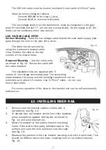
Obser ve colour coding as follows:
Connect BROWN to terminal L (Live)
Connect BLUE to terminal N (Neutral)
The low voltage leads from the transformer must be connected to the grey
push fit terminals marked T.T. (do not use a screwdriver). As the supply is AC the
leads can be connected either way around.
LOW VOLTAGE CABLE ENTRY
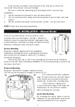
Surface Mounting
– Pass the low voltage cable beside the cold water supply pipe;
pass through the hole in the pipe entr y cover.
The cable can be secured by
using the 2 adhesive backed cable
clips. Position the clips at the top
corners of the shower base.
Recessed Mounting
– Use the cable entr y
as shown in Fig. 12. Secure the cable with
the cable restraint.
The installation kits are supplied with 5
metres of low voltage connecting lead. The connecting
leads between the pump and the isolating transformer can be
extended up to about 15 metres. Use 0.75mm
2
cable – do not use
brown/blue cable.
For normal operation of the shower, the transformer can be left permanently
switched on.
10. INSTALLING RISER RAIL
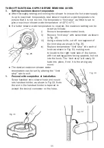
1.
Remove riser rail bracket location collars with a
screwdriver, see Fig. 13.
2.
To detach riser rail bracket covers from their brackets,
press screwdriver against locking tab, as shown in
Fig. 14, and push bracket out.
3.
Move the position of the bottom bracket mounting
holes. If the wall is tiled apply adhesive tape to the
sur face and mark the hole positions onto the tape,
see Fig. 15.
4.
Measure the position of the top bracket mounting hole with a spirit level. This
should be 558mm above the lower mounting hole of the bottom bracket,
Fig. 16.
Fig. 13
7
Fig. 12
Fig. 8


