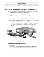
WATEROUS ARIZONA
DOCUMENT TITLE:
150-70 / 200-100 Installation
DOC. NO.
REV NO. 1
ISSUE DATE: 6/17/2010
PAGE 15 of 38
SECTION 5. OPTIONAL PROGRAMMABLE VALVE
CONTROLLER
The new and improved valve controller uses leading edge microchip technology to provide the
user with programmable valve positioning that is both accurate and repeatable.
Repeatability is assured with new "overshoot" programming, thus eliminating gear-lash and valve
coupler slop. An oversized, 3-digit, alphanumeric display conveys the position in a 0 to 100%
format with three field programmable set-points. Each set-point as well as 0 and 100% (valve full
open and full closed) is named to the users request with up to three alphanumeric characters.
Factory defaults unless specified by the customer are: CLS, LOW, Mid, Hi, and OPN. All of these
positions are easily recalled with one touch of the OPEN / CLOSE switch.
A. Operation
Two military grade toggle switches make up the users controls. The switches allow the user
to not only adjust the valve to any given position but program the position of each set-point as
well. The INCREASE/ DECREASE switch allows the user to adjust valve position by one
percentage point at a time towards open or close. The OPEN/ CLOSE switch gives one touch
access to each of the set-points.
B. Programming
Each of the three programmable set-points corresponds to a value within the 0 to 100%
range. The value for each set-point is easily adjusted by using both toggle switches.
For example:
1. To adjust the value for the LOW set-point, use the OPEN/CLOSE switch to recall the set-
point without releasing the switch.
2. After three seconds, the set-point name will change to its corresponding value on the
display.
3. While maintaining activation of the OPEN/ CLOSE switch, use the
INCREASE/DECREASE switch to adjust the value up or down as desired.
4. Each set-point is programmable in the same manner.
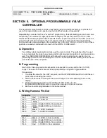
C. Wiring Harness Pin-Out
Controller
Pin 1
Red
+12VDC IN
Pin 2
Black
-12VDC IN
Pin 3
Blank
Pin 4
Green Digital COM in, from actuator
Pin 5
White
Digital COM out, to actuator
Pin 6
Blank
Pin 7
Black
-12VDC to actuator
Pin 8
Red
+12VDC to actuator
Actuator
Pin 1
Black
-12VDC in, from controller
Pin 2
Green Digital COM out, to controller
Pin 3
White
Digital COM in, from controller
Pin 4
Red
+12VDC in, from controller


