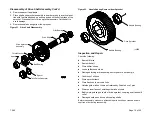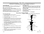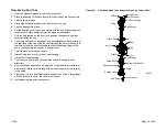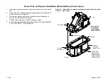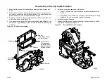
Figure 41. Installing the Chain
1.
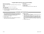
Wrap the chain around the drive and driven sprockets making sure
everything meshes and then lace the joining ends together using the
connecting pin set (
see Figure 41
).
2.
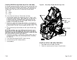
Insert the connecting pin rocker partway through the holes in the join
ing end links being careful of orientation (
see
Figure 43
). The connect
ing rocker must be on the side of the guide link opposite the joining
end with the connecting rockers wide curved surface towards the
center of the hole.
3.
Insert the connecting pin assembly along side the connecting rocker.
The two wide curved surfaces of the connecting pin and connecting
rocker must face each other.
4.
After the connecting pin assembly and connecting rocker have been
pushed all the way through the joining ends of the chain, insert the
spirol pin into the open hole at the end of the connecting pin assembly
(
see Figure 43
). Make sure the spirol pin overlaps the connecting
rocker.
5.
Check chain for proper tension. Check deflection half-way between the
drive sprocket and driven sprocket (see chart below for maximum
deflection). Replace chain if deflection is greater than those displayed
in the chart below.
T-360
Page 26 of 35
Optional Electronic Tachometer
1.
Install the O-ring onto the tachometer pick-up.
2.
Rotate drive shaft until tach tooth lines up with the tach opening.
3.
Install the tachometer pick-up into the drive shaft housing until it con
tacts the tach pulse generator. Turn back 1/2 turn.
4.
Tighten hex nut.
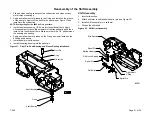
Figure 40. Optional Electronic Tachometer
Pick-Up
O-ring
Hex Nut
Drive Shaft Housing
IL2530
Installing the Chain
Drop
Max Deflection (In.)
(Both Directions)
B
1.75
C
1.75
D
1.75
E
2.0
F
2.0

