T-360
Page 32 of 35
Coupling Shaft Housing Assembly to Case Assembly
The driveline assembly was factory shimmed to limit the axial float of the drive
line. If any of the drive line parts have been changed, it may be necessary to
change the total thickness of shims between the coupling shaft housing and
the transmission case. Shims are color coded for thickness as follows:
.005"
Blue
.007"
Natural
.010"
Brown
The correct thickness of shims can be determined as follows:
1.
Install coupling shaft and housing assembly with no O-ring or shims
between the housing and case. Lightly tighten the cap screws evenly
and tap the end of the coupling shaft with a soft mallet to force the
drive line all the way forward. Do not overtighten causing bending or
breakage of the coupling shaft housing.
2.
Measure the gap between the housing and case in several places to
assure a uniform gap and add .005 in. This will be the total thickness
of shims needed to provide the recommended axial float of .005 - .010
in.
3.
Remove the coupling shaft assembly from the case after measuring
the gap.
NOTE: Field conditions may make it difficult to determine the correct
amount of shims. If in doubt, add another .005 in. shims. No harm will
result from a small amount of additional axial float but bearing life will be
shortened if bearings are excessively preloaded.
4.
Install the correct amount of shims on the coupling shaft housing or if
all original parts are being used, reinstall original shims on coupling
shaft housing.
5.
Coat O-ring with grease and install O-ring on housing.
6.
Install the coupling shaft housing assembly.
7.
Install fasteners.
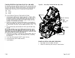
Figure 50. Assembling Coupling Shaft Housing to Case
Shims
(.005 - .010”)
Axial float
Lock Washer
Hex Hd Screw
Breather
Hose Assembly
Breather and Hose Assembly Installation
1.
Apply thread sealer to breather and install.
2.
Connect hose assembly from the cap to the mid-section.


