background image

40 

|

 56

Safety

Introduction

Product Overview

Installation

Operation

Maintenance

Connecting to Apparatus Power

3

3

2

2

1

1

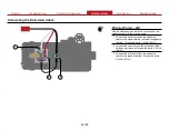
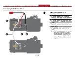
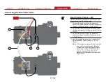
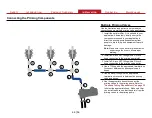
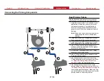
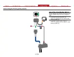
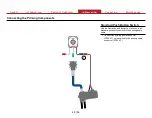
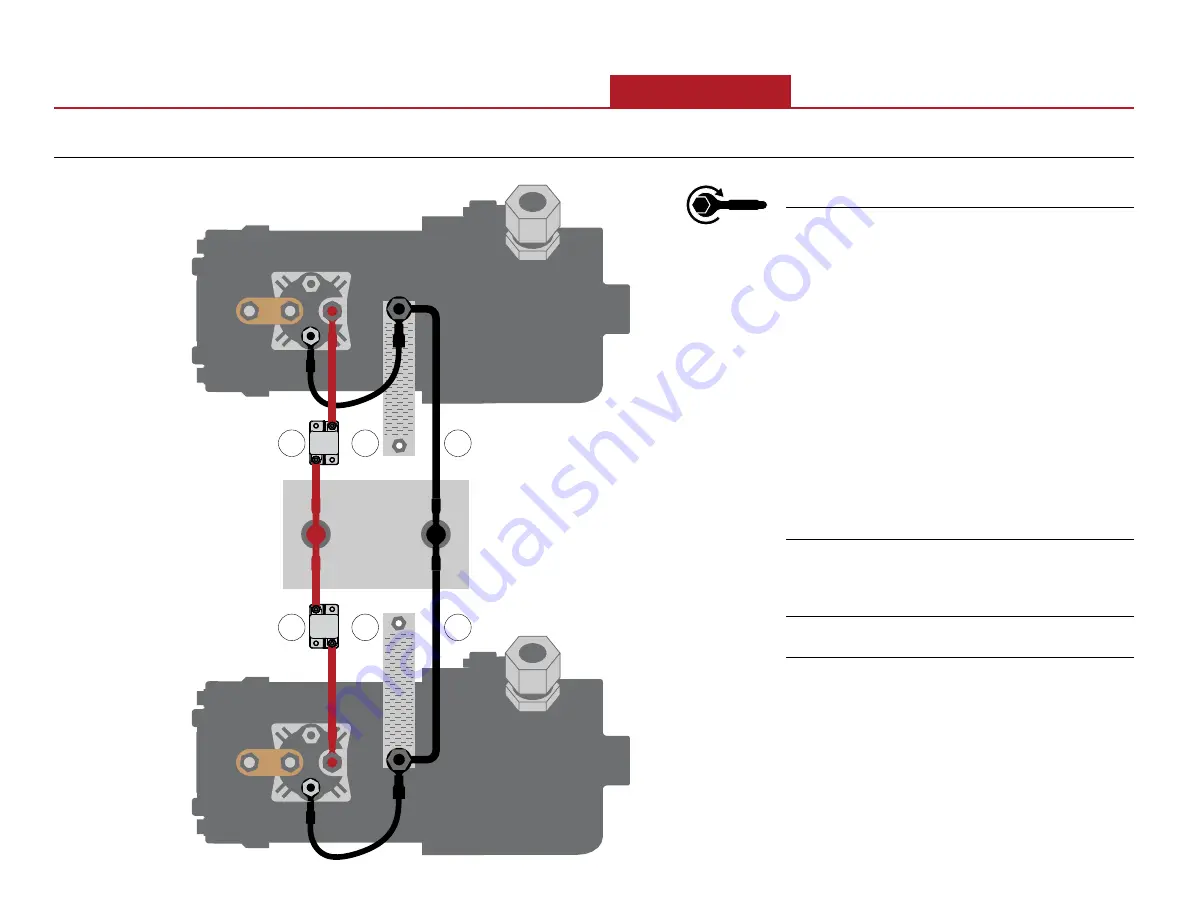
Dual Priming Pumps—24V

Use the illustration and instructions to connect the a 

dual priming pump application to apparatus power. 

Refer to

 F-2825 Wiring Best Practices

 instruction, 

available at 

waterousco.com

.

Include the following when installing the priming 

pump:

• 

The 12V priming pump draws 325 amps of current 

and the 24V priming pump draws 170 amps of 

current. Make sure your wiring is rated for the 

current draw in your application.

• 

Make sure that you include adequate circuit 

protection.

• 

It is recommended that you isolate the priming 

pump power and ground circuits for best 

performance.

• 

Provide flyback voltage protection if required by 

your application.

1 Connect apparatus power to the priming pump 

power terminal. Make sure that you include an 

appropriately sized breaker in the circuit. Torque 

the nut on the priming pump to


4.5 ft-lb (6 N∙m).

2 Connect a ground strap from the priming pump 

ground terminal to the apparatus frame.

3 Connect apparatus ground to the priming pump 

ground terminal. Torque the nut on the priming 

pump to


4.5 ft-lb (6 N∙m).

Summary of Contents for VPO Priming System

Page 1: ...Waterous Company 125 Hardman Avenue South South Saint Paul MN 55075 651 450 5000 www waterousco com VPO Priming System Installation Operation and Maintenance Form Number F 2996 Issue Date Mar 30 2023...

Page 2: ......

Page 3: ...quirements 26 Auto Prime Switch Cutout Dimensions 27 Standard Push Button Switch Dimensions 28 Oversized Push Button Switch Dimensions 29 Priming Pump Dimensions 30 Panel Cutout and Mounting Holes 31...

Page 4: ...nt if you are not familiar with the tools and skills needed to safely perform the required procedures proper installation is the responsibility of the purchaser Do not operate the equipment when safet...

Page 5: ...this document Introduction This section is an overview of the document Product Overview This section describes the components that make up the system Installation This section describes the installati...

Page 6: ...rdered together with the pump and transmission depending on the configuration the priming pump VPO priming valve VAP hose and panel cable are installed at the factory Otherwise components are shipped...

Page 7: ...stalled components in your application may include the following items Auto Prime Switch Standard Push Button Switch Oversized Push Button Switch Switch Cable 70 inches Panel Plate Priming Pump Outlet...

Page 8: ...Pump Overview There are 3 panel switch options available that operate the priming system Auto Prime Switch Auto prime with integrated push to prime operation Standard Push Button Switch Standard push...

Page 9: ...llation Operation Maintenance Multiple Priming Valve System Overview Your application may include up to 6 priming valves each operated by a dedicated switch and solenoid This allows the system to prim...

Page 10: ...10 56 Safety Introduction Product Overview Installation Operation Maintenance Dual Priming Pump System Overview Your application may include 2 priming pumps controlled by a single push button switch...

Page 11: ...Notes...

Page 12: ...duction Product Overview Installation Operation Maintenance Auto Prime Switch This allows you to manually or automatically prime the pump When auto prime is enabled the pump is primed to 10 psi 0 7 Ba...

Page 13: ...e This contains the electronic components 4 Mounting holes Enclosure This mounts the enclosure to the apparatus 5 Pressure switch connector This connects to the pressure switch DT06 2S 6 Priming valve...

Page 14: ...Mounting holes This mounts the switch to the apparatus 2 Prime button This activates the priming operation 3 Additional panel connector This connects to the next switch when applicable DT06 4S Pin 1 1...

Page 15: ...Button Switch This allows you to manually prime the pump 3 1 2 Feature Feature Description Description 1 Mounting holes This mounts the switch to the apparatus 2 Prime button This activates the primin...

Page 16: ...connected to the white extension cable wire 3 Ground terminal This is connected to the black extension cable wire 4 Mounting holes This mounts the priming pump to the transmission bracket 5 Inlet This...

Page 17: ...e extension cable wire 3 Ground terminal This is connected to the black extension cable wire the 24V incorporates an additional jumper wire 4 Mounting holes This mounts the priming pump to the transmi...

Page 18: ...Maintenance Pressure Switch This facilitates the auto prime operation 1 2 Feature Feature Description Description 1 Connector This connects to the auto prime switch DT04 2P cable length 10 inches 254...

Page 19: ...ed from each other Only used with single priming pump multiple priming valve applications 2 1 3 Feature Feature Description Description 1 Connector This connects to the switch DTM06 2S cable length 6...

Page 20: ...g hardware This mounts the priming valve to the fire pump intake or priming valve base 2 Priming valve top This is the top of the priming valve 3 Priming valve outlet This connects to the priming pump...

Page 21: ...ump Cable This connects the push button switch to the priming pump 1 3 2 Feature Feature Description Description 1 Priming pump connections This connects to the priming pump 2 Cable This cable length...

Page 22: ...iming valve solenoid install location Note The inclusion of this cable is dependent on your configuration It is also available separately if required by your application 2 1 3 Feature Feature Descript...

Page 23: ...s extends the cable length of the priming pump cable 2 1 3 Feature Feature Description Description 1 Connector This connects to the priming pump solenoid or a solenoid equipped priming valve DT04 4P 2...

Page 24: ...ssure switch install location Note The inclusion of this cable is dependent on your configuration It is also available separately if required by your application 2 1 3 Feature Feature Description Desc...

Page 25: ...e you begin the installation NOTICE Before Operation Read and understand all the instructions provided Check all fluid levels and replenish if necessary Remove all shipping plugs and install the opera...

Page 26: ...led components The following instructions describe how to install and connect each of the components in the priming system Use the instruction appropriate to your application to install your system In...

Page 27: ...ling the Auto Prime Switch 1 Panel Cutout and Mounting Holes Use the illustration and instruction to create the cutout and mounting holes for the auto prime switch 1 Create the cutout and drill the mo...

Page 28: ...ation Operation Maintenance Installing the Auto Prime Switch 1 Positioning the Switch Use the illustration and instruction to mount the auto prime switch on the panel 1 Route the plugs and enclosure t...

Page 29: ...the Auto Prime Switch 1 2 Mounting the Enclosure Use the illustration and instructions to mount the auto prime switch to the panel 1 Use a clean rag and alcohol to clean the area where you intend to m...

Page 30: ...rview Installation Operation Maintenance Installing the Auto Prime Switch 1 Mounting the Panel Use the illustration and instruction to mount the auto prime switch on the panel 1 Use locally sourced mo...

Page 31: ...1 Use the illustration and instructions to install the standard push button switch 1 Create the cutout and drill the mounting holes for the switch Refer to Standard Push Button Switch Dimensions on p...

Page 32: ...2 1 Use the illustration and instructions to mount the oversized push button switch 1 Create the cutout and drill the mounting holes for the switch Refer to Oversized Push Button Switch Dimensions on...

Page 33: ...ration and instructions to install a remote mounted priming pump 1 Make a bracket suitable for your application to securely mount the priming pump to the apparatus Refer to Priming Pump Dimensions on...

Page 34: ...application The priming valve must be mounted above the priming pump The vacuum hose or tubing must allow water to drain from the priming valve to the priming pump If additional priming valves are ins...

Page 35: ...ng the Pressure Switch 2 1 Use the illustration and instruction to install the pressure switch The pressure switch is only required when operating the pump in auto prime mode 1 Locate a suitable 1 4 i...

Page 36: ...and instructions to install the optional priming valve solenoid 1 Remove the 6 and the M5 screws from the priming valve Note The removed screws are no longer needed re purpose recycle or discard them...

Page 37: ...ing is rated for the current draw in your application It is recommended that you isolate the priming pump power and ground circuits for best performance Make sure that you include adequate circuit pro...

Page 38: ...ing is rated for the current draw in your application Make sure that you include adequate circuit protection It is recommended that you isolate the priming pump power and ground circuits for best perf...

Page 39: ...e sure your wiring is rated for the current draw in your application Make sure that you include adequate circuit protection It is recommended that you isolate the priming pump power and ground circuit...

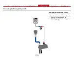
Page 40: ...e sure your wiring is rated for the current draw in your application Make sure that you include adequate circuit protection It is recommended that you isolate the priming pump power and ground circuit...

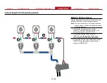
Page 41: ...extension cable to the priming pump 1 Connect the white wire from the extension cable to the signal terminal on the priming pump terminal Torque the nut to 1 5 ft lb 2 N m 2 Connect the red wire from...

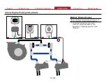
Page 42: ...extension cable to the priming pump 1 Connect the white wire from the extension cable to the signal terminal on the priming pump terminal Torque the nut to 1 5 ft lb 2 N m 2 Connect the red wire from...

Page 43: ...N m 2 Connect the red wire from the extension cable to the power terminal Torque the nut to 4 5 ft lb 6 N m 3 Connect the black wire from the extension cable to the ground terminal Torque the nut to 4...

Page 44: ...N m 2 Connect the red wire from the extension cable to the power terminal Torque the nut to 4 5 ft lb 6 N m 3 Connect the black wire from the extension cable to the ground terminal Torque the nut to 4...

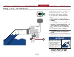
Page 45: ...e priming pump exhaust away from people to avoid injury and equipment to avoid damage Note Make sure to use a minimal bend radius and arrange the hose to allow proper draining 2 Install a 3 4 inch NPT...

Page 46: ...use a minimal bend radius and arrange the hose to allow proper draining 2 Install a 3 4 inch NPT fitting with a 3 4 inch hose connection to the priming pump inlet 3 Install a 3 4 inch NPT fitting with...

Page 47: ...se connection to the priming pump inlet 3 Install an 3 4 inch NPT fitting with a 3 4 inch hose connection to the priming valve outlet 4 Use a T fitting and the required adapters to make an assembly an...

Page 48: ...Push Button Switch Use the illustration and instructions to connect the standard push button switch to the priming pump cable 1 Connect the priming pump connector DT04 2P on the switch to the priming...

Page 49: ...nance Connecting the Priming Components 1 Standard Push Button Switch Use the illustration and instruction to connect the standard push button switch to the priming pump cable 1 Connect the priming pu...

Page 50: ...ance Connecting the Priming Components 1 Oversized Push Button Switch Use the illustration and instruction to connect the oversized push button switch to the priming pump cable 1 Connect the priming p...

Page 51: ...cs Note You can connect up to 6 solenoid controlled priming valves each with a dedicated switch in your application 1 Connect the priming pump connector DT04 2P on the push button switch to the primin...

Page 52: ...onnecting the Priming Components 1 Multiple Priming Pumps Use the illustration and instruction to connect the push button switch to the priming electronics 1 Connect the priming pump connector DT04 2P...

Page 53: ...5 seconds An additional 15 seconds may be required for a 4 inch or larger intake If your pump does not prime in that time verify that all openings are closed Allow 1 minute of cool down time between p...

Page 54: ...r pump for 45 seconds An additional 15 seconds may be required for a 4 inch or larger intake If your pump does not prime in that time verify that all openings are closed Allow 1 minute of cool down ti...

Page 55: ...as required NFPA testing X Test per NFPA requirements Vacuum Testing Perform the following test monthly Remove all caps except openings without valves Close all intake discharge drain and similar open...

Page 56: ...Waterous Company 125 Hardman Avenue South South Saint Paul MN 55075 651 450 5000 www waterousco com...

Reviews: