Tip:
Place the column gripping tool onto the column to loosen the dual-threaded fitting.
9.
Set aside the APH assembly for discarding.
10. Unpack the new APH assembly.
Note:
For instructions on replacing the APH retainer clip, see
11. Remove the O-ring retainer from the inlet end of the APH inlet tubing and connect the inlet
tubing to port 6 of the sample manager injection valve.
Note:
For installation instructions, see
12. Route the APH inlet tubing behind the hinge of the fluidics compartment door in the sample
manager and into the slot that leads to the column trough.
13. Loosen the #2 locking cap nut on the APH before assembling the column or in-line filter.
Note:
For instructions on how to install the column in-line filter, see
14. Connect the column assembly to the APH.
Note:
For installation instructions, see
Dual threaded fitting with locking cap nut
.
15. Connect the column outlet tubing to the column.
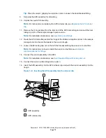
16. Insert the APH assembly into the APH retainer clip and push the column assembly into the
trough.
Figure 3–9: Inserting the APH assembly into the retainer clip
APH assembly
APH retainer clip
December 4, 2019, 715005052 Version 02 (previously released as Rev.B)
Page 79


