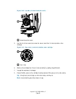
Figure 3–8: Inlet manifold outlet-tubing fitting
1
2
3
Inlet manifold outlet-tubing fitting
Inlet manifold
i
2
Valve
5.
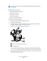
Use the 1/4-inch open-end wrench to disconnect the inlet-tubing fittings from the inlet
manifold.
Figure 3–9: Inlet-tubing fittings on manifold
1
Inlet-tubing fitting (4)
6.
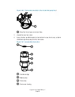
Remove the inlet manifold from the mounting bracket.
7.
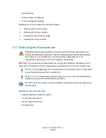
Ensuring its groove faces forward, place the new inlet manifold in the mounting bracket.
Figure 3–10: Inlet manifold groove
1
Groove
August 8, 2016, 715005050 Rev. C
Page 52


