2-2
Preparing System Hardware
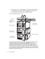
The power and status LEDs change as follows:
•
Each LED shows red for a few seconds, except for the power LEDs.
•
During initialization, these LEDs flash green:
–
Auxiliary solvent manager’s flow LED
–
Binary solvent manager’s flow LED
–
Sample manager’s run LED
–
Detector’s lamp LED
•
After the modules are successfully powered-on, each one’s power
LED shows steady green. The auxiliary solvent manager’s and
binary solvent manager’s flow LEDs and the sample manager’s run
LED are unlit. The detector’s lamp LED shows steady green.
2.
Power-on the workstation. You can monitor the nanoACQUITY UPLC
Console for messages and visual signals.
3.
Start MassLynx.
Monitoring startup tests
These startup tests run when you power-on the workstation.
•
CPU board
•
Memory (RAM and ROM)
•
External communication system (Ethernet)
•
Clock
Monitoring the LEDs of system instruments
Light emitting diodes (LEDs) on each system module indicate the module’s
state of functioning. The LEDs are specific to each module, so the significance
of their various colors and modes can differ from one module to another.
Power LED
The power LED, on the left side of a module’s front panel, indicates when the
module is powered-on or powered-off.
Summary of Contents for nanoACQUITY UPLC
Page 7: ...vii ...
Page 16: ...xvi ...
Page 20: ...xx Table of Contents ...
Page 32: ...1 12 System Overview ...


