TM 11-5825-278-12-2
CHAPTER 1
I N T R O D U C T I O N
Section I.
GENERAL INFORMATION
SECTION CONTENTS
1-3.
1-4.
1-5.
1-6.
1-7.
1-8.
1-9.
1-10.
1-11.
Scope
Consolidated Index of Army Publications
and Blank Forms
Maintenance Forms, Records and Reports
Hand Receipt (-HR) Manuals
Destruction of Army Materiel to Prevent Enemy Use
Preparation for Storage or Shipment
Nomenclature Cross-Reference List
Reporting Equipment Improvement Recommendations
Warranty Information
List of Abbreviations
Glossary
Page
1-1
1-2
1-2
1-2
1-2
1-3
1-4
1-4
1-4
1-5
1-1. SCOPE
a.
Type of Manual.
This is an Operator and Organizational
Maintenance technical manual.
b.
Model Numbers and Equipment Names.
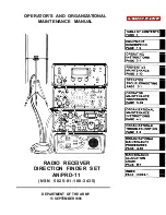
The Radio Receiver
Direction Finder Set, AN/PRD-11 consists of a Direction Finder
Antenna, AS-3732/PRD-11 or AS-3733/PRD-11, a Panoramic Indicator,
IP-1355/GRR-8(V), a Receiver,
AN/GRR-8(V), and a Processor Display
Control, C-11495/PRD-11.
This group of equipment will be referred
to in this manual as the direction finder-set.
The direction finder
antenna will be known as the df antenna, the panoramic indicator as
the signal monitor, the receiver as the receiver and the processor
display control as the df processor.
c.
Purpose of Equipment.
The direction finder set detects and
displays radio signal frequencies and provides line of bearing
information for the location of transmitting antennas.
1-2.
CONSOLIDATED INDEX OF ARMY PUBLICATIONS
Refer to the latest issue of DA Pam 310-1
there are new editions, changes or additional
pertaining to the equipment.
AND BLANK FORMS
to determine whether
publications
1-1
Summary of Contents for AN/PRD-11
Page 2: ......
Page 6: ......
Page 10: ...TM 11 5825 278 12 2 RADIO RECEIVER DIRECTION FINDER SET AN PRD 11 1 0...
Page 18: ......
Page 21: ...1 13 LOCATION AND TM DESCRIPTION OF MAJOR COMPONENTS 11 5825 278 12 2 Continued 1 11...
Page 23: ...TM 11 5825 278 12 2 1 13 LOCATION AND DESCRIPTION OF MAJOR COMPONENTS Continued 1 13...
Page 32: ...TM 11 5825 278 12 2 2 2 RECEIVER CONTROLS INDICATORS AND CONNECTORS 2 2...
Page 33: ...TM 11 5825 278 12 2 2 2 RECEIVER CONTROLS INDICATORS AND CONNECTORS Continued 2 3...
Page 34: ...TM 11 5825 278 12 2 2 2 RECEIVER CONTROLS INDICATORS AND CONNECTORS Continued 2 4...
Page 35: ...TM 11 5825 278 12 2 2 2 RECEIVER CONTROLS INDICATORS AND CONNECTORS Continued 2 5...
Page 36: ...TM 11 5825 278 12 2 2 3 DF PROCESSOR CONTROLS INDICATORS AND CONNECTORS 2 6...
Page 37: ...TM 11 5825 278 12 2 2 3 DF PROCESSOR CONTROLS INDICATORS AND CONNECTORS Continued 2 7...
Page 38: ...TM 11 5825 278 12 2 2 3 DF PROCESSOR CONTROLS INDICATORS AND CONNECTORS Continued 2 8...
Page 39: ...TM 11 5825 278 12 2 2 4 SIGNAL MONITOR CONTROLS INDICATORS AND CONNECTORS 2 9...
Page 40: ...TM 11 5825 278 12 2 2 4 SIGNAL MONITOR CONTROLS INDICATORS AND CONNECTORS Continued 2 10...
Page 41: ...TM 11 5825 278 12 2 2 4 SIGNAL MONITOR CONTROLS INDICATORS AND CONNECTORS Continued 2 11...
Page 42: ...TM 11 5825 278 12 2 2 5 ANTENNA CONNECTORS AND INDICATOR 2 12...
Page 46: ...TM 11 5825 278 12 2 2 9 SITE SELECTION Continued 2 16...
Page 48: ...TM 11 5825 278 12 2 2 9 SITE SELECTION Continued 2 18...
Page 100: ......
Page 107: ...TM 11 5825 278 12 2 2 11 INITIAL ADJUSTMENTS Continued GO ON TO SHEET 3 2 77...
Page 115: ...TM 11 5825 278 12 2 2 12 OPERATING PROCEDURES Continued GO ON TO SHEET 3 2 85...
Page 121: ...TM 11 5825 278 12 2 2 12 OPERATING PROCEDURES Continued 2 91...
Page 123: ...TM 11 5825 278 12 2 2 12 OPERATING PROCEDURES Continued 2 93...
Page 127: ...TM 11 5825 278 12 2 2 12 OPERATING PROCEDURES Continued 2 97...
Page 129: ...TM 11 5825 278 12 2 2 12 OPERATING PROCEDURES Continued GO ON TO SHEET 2 2 99...
Page 184: ......
Page 204: ...2 10 2 11a 4 11a TM 11 5825 278 12 2 4 9 TROUBLESHOOTING PROCEDURES Continued k 4 20...
Page 248: ...TM 11 5825 278 12 2 4 11 d MAINTENANCE PROCEDURES Continued 4 64...
Page 251: ...TM 11 5825 278 12 2 4 13 PACKING INSTRUCTIONS Continued 4 67...
Page 254: ......
Page 260: ...TM 11 5825 278 12 2 B 4 Section II MAINTENANCE ALLOCATION CHART...
Page 261: ...TM 11 5825 278 12 2 Section II MAINTENANCE ALLOCATION CHART Continued B 5...
Page 262: ...TM 11 5825 278 12 2 Section II MAINTENANCE ALLOCATION CHART Continued B 6...
Page 263: ...TM 11 5825 278 12 2 Section II MAINTENANCE ALLOCATION CHART Continued B 7...
Page 264: ...TM 11 5825 278 12 2 Section II MAINTENANCE ALLOCATION CHART Continued B 8...
Page 265: ...TM 11 5825 278 12 2 Section II MAINTENANCE ALLOCATION CHART Continued B 9...
Page 266: ...TM 11 5825 278 12 2 Section II MAINTENANCE ALLOCATION CHART Continued B 10...
Page 267: ...TM 11 5825 278 12 2 Section III TOOL AND TEST EQUIPMENT REQUIREMENTS B 11...
Page 268: ...TM 11 5825 278 12 2 Section III TOOL AND TEST EQUIPMENT REQUIREMENTS Continued B 12...
Page 269: ...TM 11 5825 278 12 2 Section IV REMARKS B 13...
Page 270: ...TM 11 5825 278 12 2 Section IV REMARKS Continued B 14...
Page 272: ...TM 11 5825 278 12 2 Section II COMPONENTS OF END ITEM AND BASIC ISSUE ITEMS LIST C 2...
Page 273: ...TM 11 5825 276 12 2 Section III BASIC ISSUE ITEMS C 3 C 4 blank...
Page 274: ...I...
Page 276: ...TM 11 5825 278 12 2 Section II ADDITIONAL AUTHORIZATION LIST D 2...
Page 278: ...TM 11 5825 278 12 2 Section II EXPENDABLE SUPPLIES AND MATERIALS LIST E 2...
Page 286: ......
Page 287: ......
Page 288: ......
Page 289: ......
Page 290: ......
Page 291: ......
Page 292: ......
Page 293: ......
Page 294: ......
Page 296: ......
Page 297: ......
Page 298: ...059582...

