TM 11-5025-278-12-2
4-9.
TROUBLESHOOTING PROCEDURES
Organizational troubleshooting of the direction finder set is
authorized for an EW/Intercept Systems Repairer only.
The test
equipment and materials that may be required for fault location and
their nomenclature are provided in the following table.
Maintenance Supplies
Identification
Test Equipment
Multimeter
AN/PSM-45
RF Voltmeter
Boonton 92C
Angle Simulator
High Frequency Probe
Boonton 91-12F
Test Lead Set
Simpson No. 00577
Materials/Parts
Battery, Dry
BA-4386/PRC-25
Battery, Storage
BB-586/U
Battery, D-Cell
BA-30
Fuse, 1 amp, 3AC (71400) AGC1
5920-00-280-8342
Fuse/Cartridge, 3/4 amp, 3AG SLOW
(71400) MDL 3/4
5920-00-230-9128
Receiver
AN/GRR-8(V)
Indicator, Panoramic
IP-1355/GRR-8(V)
Antenna, Direction Finder
AS-3732/PRD-11
Antenna, Direction Finder
As-3733/PRD-11
Control, Processor Display (df processor)
C-11495/PRD-11
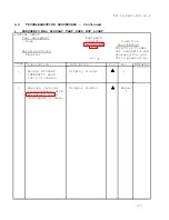
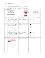
Follow these instructions when using the troubleshooting tables:
Check initial setup for the exact equipment and materials
required to perform the procedure.
Begin troubleshooting with Step 1.
Follow the directive listed in the Instruction column.
Match your results with the question asked in the
Indication column.
If the answer to the question in the Indication column is
yes, look in the Yes column and proceed to the step listed.
If the
answer to the question in the Indication column is no, look in the
No column and proceed to the step listed .
Continue through the table until
or
appears in the
Yes or No column.
A triangle means to stop
troubleshooting because the malfunction should now be corrected. A
box means to refer back to the symptom index.
Read any comments related to troubleshooting procedures in
the Remarks column.
4-5
Summary of Contents for AN/PRD-11
Page 2: ......
Page 6: ......
Page 10: ...TM 11 5825 278 12 2 RADIO RECEIVER DIRECTION FINDER SET AN PRD 11 1 0...
Page 18: ......
Page 21: ...1 13 LOCATION AND TM DESCRIPTION OF MAJOR COMPONENTS 11 5825 278 12 2 Continued 1 11...
Page 23: ...TM 11 5825 278 12 2 1 13 LOCATION AND DESCRIPTION OF MAJOR COMPONENTS Continued 1 13...
Page 32: ...TM 11 5825 278 12 2 2 2 RECEIVER CONTROLS INDICATORS AND CONNECTORS 2 2...
Page 33: ...TM 11 5825 278 12 2 2 2 RECEIVER CONTROLS INDICATORS AND CONNECTORS Continued 2 3...
Page 34: ...TM 11 5825 278 12 2 2 2 RECEIVER CONTROLS INDICATORS AND CONNECTORS Continued 2 4...
Page 35: ...TM 11 5825 278 12 2 2 2 RECEIVER CONTROLS INDICATORS AND CONNECTORS Continued 2 5...
Page 36: ...TM 11 5825 278 12 2 2 3 DF PROCESSOR CONTROLS INDICATORS AND CONNECTORS 2 6...
Page 37: ...TM 11 5825 278 12 2 2 3 DF PROCESSOR CONTROLS INDICATORS AND CONNECTORS Continued 2 7...
Page 38: ...TM 11 5825 278 12 2 2 3 DF PROCESSOR CONTROLS INDICATORS AND CONNECTORS Continued 2 8...
Page 39: ...TM 11 5825 278 12 2 2 4 SIGNAL MONITOR CONTROLS INDICATORS AND CONNECTORS 2 9...
Page 40: ...TM 11 5825 278 12 2 2 4 SIGNAL MONITOR CONTROLS INDICATORS AND CONNECTORS Continued 2 10...
Page 41: ...TM 11 5825 278 12 2 2 4 SIGNAL MONITOR CONTROLS INDICATORS AND CONNECTORS Continued 2 11...
Page 42: ...TM 11 5825 278 12 2 2 5 ANTENNA CONNECTORS AND INDICATOR 2 12...
Page 46: ...TM 11 5825 278 12 2 2 9 SITE SELECTION Continued 2 16...
Page 48: ...TM 11 5825 278 12 2 2 9 SITE SELECTION Continued 2 18...
Page 100: ......
Page 107: ...TM 11 5825 278 12 2 2 11 INITIAL ADJUSTMENTS Continued GO ON TO SHEET 3 2 77...
Page 115: ...TM 11 5825 278 12 2 2 12 OPERATING PROCEDURES Continued GO ON TO SHEET 3 2 85...
Page 121: ...TM 11 5825 278 12 2 2 12 OPERATING PROCEDURES Continued 2 91...
Page 123: ...TM 11 5825 278 12 2 2 12 OPERATING PROCEDURES Continued 2 93...
Page 127: ...TM 11 5825 278 12 2 2 12 OPERATING PROCEDURES Continued 2 97...
Page 129: ...TM 11 5825 278 12 2 2 12 OPERATING PROCEDURES Continued GO ON TO SHEET 2 2 99...
Page 184: ......
Page 204: ...2 10 2 11a 4 11a TM 11 5825 278 12 2 4 9 TROUBLESHOOTING PROCEDURES Continued k 4 20...
Page 248: ...TM 11 5825 278 12 2 4 11 d MAINTENANCE PROCEDURES Continued 4 64...
Page 251: ...TM 11 5825 278 12 2 4 13 PACKING INSTRUCTIONS Continued 4 67...
Page 254: ......
Page 260: ...TM 11 5825 278 12 2 B 4 Section II MAINTENANCE ALLOCATION CHART...
Page 261: ...TM 11 5825 278 12 2 Section II MAINTENANCE ALLOCATION CHART Continued B 5...
Page 262: ...TM 11 5825 278 12 2 Section II MAINTENANCE ALLOCATION CHART Continued B 6...
Page 263: ...TM 11 5825 278 12 2 Section II MAINTENANCE ALLOCATION CHART Continued B 7...
Page 264: ...TM 11 5825 278 12 2 Section II MAINTENANCE ALLOCATION CHART Continued B 8...
Page 265: ...TM 11 5825 278 12 2 Section II MAINTENANCE ALLOCATION CHART Continued B 9...
Page 266: ...TM 11 5825 278 12 2 Section II MAINTENANCE ALLOCATION CHART Continued B 10...
Page 267: ...TM 11 5825 278 12 2 Section III TOOL AND TEST EQUIPMENT REQUIREMENTS B 11...
Page 268: ...TM 11 5825 278 12 2 Section III TOOL AND TEST EQUIPMENT REQUIREMENTS Continued B 12...
Page 269: ...TM 11 5825 278 12 2 Section IV REMARKS B 13...
Page 270: ...TM 11 5825 278 12 2 Section IV REMARKS Continued B 14...
Page 272: ...TM 11 5825 278 12 2 Section II COMPONENTS OF END ITEM AND BASIC ISSUE ITEMS LIST C 2...
Page 273: ...TM 11 5825 276 12 2 Section III BASIC ISSUE ITEMS C 3 C 4 blank...
Page 274: ...I...
Page 276: ...TM 11 5825 278 12 2 Section II ADDITIONAL AUTHORIZATION LIST D 2...
Page 278: ...TM 11 5825 278 12 2 Section II EXPENDABLE SUPPLIES AND MATERIALS LIST E 2...
Page 286: ......
Page 287: ......
Page 288: ......
Page 289: ......
Page 290: ......
Page 291: ......
Page 292: ......
Page 293: ......
Page 294: ......
Page 296: ......
Page 297: ......
Page 298: ...059582...

