background image

TM 11-5825-278-12-2

4-9.

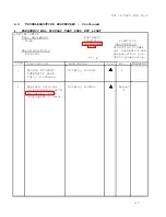
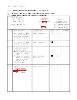
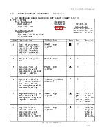
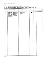
TROUBLESHOOTING PROCEDURES - Continued

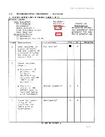
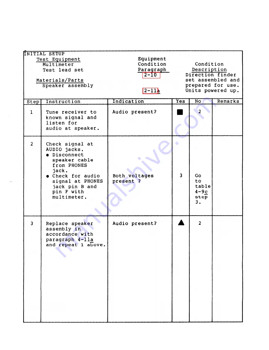
j. NO AUDIO WHEN SPEAKER ASSEMBLY IS USED

4-19

Summary of Contents for AN/PRD-11

Page 1: ...3 1 PAGE 3 19 PAGE 4 1 PAGE 4 3 PAGE 4 40 PAGE B 1 PAGE INDEX 1 OPERATOR S AND ORGANIZATIONAL MAINTENANCE MANUAL TM 11 5825 278 12 2 RADIO RECEIVER DIRECTION FINDER SET AN PRD 11 NSN 5825 01 188 3435...

Page 2: ......

Page 3: ...eme caution when recharging by ensuring proper electrical connections and keeping the charger away from other equipment that may spark and cause an explosion Do not remove the protective covers to the...

Page 4: ...o not discard discharged batteries with combustibles Do not remove the protective covers to any of the units Voltages within these units can cause electrical shock Turn off all power to the units befo...

Page 5: ...oose circles sized to fit within the antenna carrying bag If the cables are too tightly wrapped they will break Before lowering antenna arm be sure antenna mast cables are free of locking thumbscrews...

Page 6: ......

Page 7: ...on I II III CHAPTER 2 Section I II III IV CHAPTER 3 Section I II III IV CHAPTER 4 Section I II III IV V VI HOW TO USE THIS MANUAL INTRODUCTION General Information Equipment Description Principles of O...

Page 8: ...2 2 APPENDIX A B C D E REFERENCES MAINTENANCE ALLOCATION CHART COMPONENTS END ITEMS AND BASIC ISSUE ITEMS ADDITIONAL AUTHORIZATION LIST EXPENDABLE SUPPLIES AND MATERIALS LIST INDEX Page A 1 B 1 C 1 D...

Page 9: ...divided into chapters sections and paragraphs which are numbered sequentially Each large section begins with a Section Contents which lists each paragraph by title and page number Each paragraph that...

Page 10: ...TM 11 5825 278 12 2 RADIO RECEIVER DIRECTION FINDER SET AN PRD 11 1 0...

Page 11: ...Direction Finder Set AN PRD 11 consists of a Direction Finder Antenna AS 3732 PRD 11 or AS 3733 PRD 11 a Panoramic Indicator IP 1355 GRR 8 V a Receiver AN GRR 8 V and a Processor Display Control C 11...

Page 12: ...ands for Hand Receipt The TM 11 5825 278 10 2HR consists of preprinted hand receipts DA Form 2062 that list end item related equipment you must account for As an aid to property accountability additio...

Page 13: ...charger Power Supply BA PP 7566 GRR 8 V Df antenna Antenna Direction Finder AS 3732 PRD 11 and Antenna Direction Finder AS 3733 PRD 11 Df processor Control Processor Display C 11495 PRD 11 Direction...

Page 14: ...Johnson Company for a period of two years following delivery It starts on the date found in block 23 DA Form 2408 9 in the logbook This warranty may contain repair restrictions Report all defects in m...

Page 15: ...a that detects rf signals Automatic gain control agc A circuit which automatically maintains the output volume of receiver regardless of the signal strength Bandwidth The range within the limits of a...

Page 16: ...r maximum reception Frequency The number of complete cycles in one second of alternating current Frequency band A continuous and specific range of frequencies High bay The elements of the df antenna t...

Page 17: ...a receiver by reducing its gain Target transmitter The source of radio transmissions in which a direction finder set is monitoring Threshold The point at which a signal is first detected Trace The pat...

Page 18: ......

Page 19: ...EQUIPMENT CHARACTERISTICS CAPABILITIES AND FEATURES CHARACTERISTICS Battery operated Portable weatherproof and shockproof Usable as a manpack or mounted in a vehicle CAPABILITIES AND FEATURES Detects...

Page 20: ...isplay of signal activity of the tuned frequency Aids the operator in determining the amplitude of the signal being received 3 DF PROCESSOR Provides switching signals to the antenna and IF Input to th...

Page 21: ...1 13 LOCATION AND TM DESCRIPTION OF MAJOR COMPONENTS 11 5825 278 12 2 Continued 1 11...

Page 22: ...ted disassembled in similar antenna carrying bags Each df antenna component is stored in a specific area of the antenna carrying bag as shown here The carrying bag for the AS 3733 PRD 11 has additiona...

Page 23: ...TM 11 5825 278 12 2 1 13 LOCATION AND DESCRIPTION OF MAJOR COMPONENTS Continued 1 13...

Page 24: ...pole length Lower bay 73 in 73 in Upper bay nonexistent 14 2 in Array diameter Lower bay 43 in 43 in Upper bay nonexistent 6 7 in Number of terminals 2 3 Weight 14 lbs 17 lbs 1 15 EQUIPMENT DATA DIMEN...

Page 25: ...ttery sources D cell alkaline BA 30 D cell nickel cadmium BB 586 U Lithium S02 BA 5598 U Dry Battery BA 4386 PRC 25 Non rechargeable Lithium BA 5598 U Source BA 30 BB 586 U BA 5598 U BA 4386 PRC 25 Op...

Page 26: ...tion 1 16 1 18 Typical Data Flow 1 18 1 19 Modes of Operation 1 19 1 17 TECHNICAL PRINCIPLES OF OPERATION The direction finder set consists of a df antenna a signal monitor a receiver and a df process...

Page 27: ...gnal monitor through the df processor for a visual waveform display of the tuned frequency Provides signal to df processor for determination of lob THE DF PROCESSOR Activates the df antenna and contro...

Page 28: ...lements in sequence Rf signals present on each turned on element is sent to the receiver 2 through the rf cable The receiver 2 through operator tuning indicates the frequency of the rf signal This sig...

Page 29: ...search and monitor frequency bands A line of bearing lob can be obtained on a transmitting antenna when operating in this mode However the lob will only supply you with direction You cannot accurately...

Page 30: ...an then plot the location of the target transmission Each direction finder station detects radio frequency signals between 5 and 500 MHz depending on its installed tuner assembly Each direction finder...

Page 31: ...CONTENTS Page 2 1 General 2 1 2 2 Receiver Controls Indicators and Connectors 2 2 2 3 Df Processor Controls Indicators and Connectors 2 6 2 4 Signal Monitor Controls Indicators and Connectors 2 9 2 5...

Page 32: ...TM 11 5825 278 12 2 2 2 RECEIVER CONTROLS INDICATORS AND CONNECTORS 2 2...

Page 33: ...TM 11 5825 278 12 2 2 2 RECEIVER CONTROLS INDICATORS AND CONNECTORS Continued 2 3...

Page 34: ...TM 11 5825 278 12 2 2 2 RECEIVER CONTROLS INDICATORS AND CONNECTORS Continued 2 4...

Page 35: ...TM 11 5825 278 12 2 2 2 RECEIVER CONTROLS INDICATORS AND CONNECTORS Continued 2 5...

Page 36: ...TM 11 5825 278 12 2 2 3 DF PROCESSOR CONTROLS INDICATORS AND CONNECTORS 2 6...

Page 37: ...TM 11 5825 278 12 2 2 3 DF PROCESSOR CONTROLS INDICATORS AND CONNECTORS Continued 2 7...

Page 38: ...TM 11 5825 278 12 2 2 3 DF PROCESSOR CONTROLS INDICATORS AND CONNECTORS Continued 2 8...

Page 39: ...TM 11 5825 278 12 2 2 4 SIGNAL MONITOR CONTROLS INDICATORS AND CONNECTORS 2 9...

Page 40: ...TM 11 5825 278 12 2 2 4 SIGNAL MONITOR CONTROLS INDICATORS AND CONNECTORS Continued 2 10...

Page 41: ...TM 11 5825 278 12 2 2 4 SIGNAL MONITOR CONTROLS INDICATORS AND CONNECTORS Continued 2 11...

Page 42: ...TM 11 5825 278 12 2 2 5 ANTENNA CONNECTORS AND INDICATOR 2 12...

Page 43: ...ERVICES a Routine services are a collection of checks and observations performed by the operator at all times Routine services are not listed in the preventive maintenance checks and services table b...

Page 44: ...PMCS PROCEDURES The PMCS table will guide you in the performance of the direction finder sets required scheduled services An explanation of each column in the table is as follows a Item Number Column...

Page 45: ...2 14 Operation of Auxiliary Equipment 2 123 Page 2 9 SITE SELECTION Selection of a df site is dependent on both tactical and technical considerations A combination of problems may occur during site s...

Page 46: ...TM 11 5825 278 12 2 2 9 SITE SELECTION Continued 2 16...

Page 47: ...erations Observing these procedures will help you choose the most practical site Choose the highest level of ground in the area Choose an area that is flat for at least 90 meters surrounding the df an...

Page 48: ...TM 11 5825 278 12 2 2 9 SITE SELECTION Continued 2 18...

Page 49: ...s transmitters when some radio waves pass through them Avoid metal objects that can cause reradiation Site vehicles should be in quadrant of least interest Radio waves can be bent as they pass from on...

Page 50: ...tracks Near chimney stacks or water towers Near wire fences PREFERRED DISTANCES FROM OBSTACLES Obstacles Distance to be Maintained Scattered trees and vegetation 185 meters Mountains or hills 5 kilome...

Page 51: ...ists of the procedures that must be performed to prepare a df antenna for operation Two crewmembers are normally needed to perform these procedures Under certain circumstances the antenna can be set u...

Page 52: ...ripod legs To access and set up the tripod follow these steps 1 Open antenna carrying bag 1 by unbuckling three fastening straps 2 and unrolling bag 1 NOTE The AS 3733 PRD 11 antenna carrying bag has...

Page 53: ...ued 4 Loosen center tension knob 5 on sliding collar 6 of tripod center column 7 by turning counterclockwise 5 Grasp tripod legs 8 below stabilizing arms 9 and pull legs open 6 Push down on stabilizin...

Page 54: ...N Do not position the tripod on a slope that is too steep to set all legs securely on ground Antenna should not lean more than 30 from vertical NOTE Extend the legs to maximum length when possible to...

Page 55: ...d in the antenna carrying bag If a second crewmember is present he or she will assist the first by performing procedures indicated below 1 Free antenna mast 1 by pulling five quick release straps 2 on...

Page 56: ...t 4 on edge of antenna carrying bag 5 and hold antenna upright mast 4 NOTE Second crewmember will perform 4 below Both crewmembers will perform 5 and 6 below 4 Remove eight short elements from antenna...

Page 57: ...EPARATION FOR USE Continued 7 Lift antenna mast 8 and slide onto tripod mount 9 8 Handtighten three locking screws 10 at base of antenna mast 11 by turning clockwise Locking screws will not be flush w...

Page 58: ...ION Do not force element into antenna box Aluminum tip will bend and may not be able to be removed 10 Holding each end of ele ment 12 insert twist lock connector end of element 14 into antenna element...

Page 59: ...ew 18 clicks into place NOTE Thumbscrew will be locked into place on mounting plate when antenna arms thumbscrew is not flush are fully extended against the antenna arm ensure thumbscrew is alined wit...

Page 60: ...20 into lower section of antenna element box 21 on extended arm 19 17 Turn element 20 clockwise until flush with antenna element box 21 18 Continue turning element 20 1 4 turn clockwise to lock into...

Page 61: ...his should be done before the cables are connected to the antenna 1 Remove df 1 and rf 2 cables from antenna carrying bag 3 NOTE AS 3722 PRD 11 has two cables and AS 3733 PRD 11 antenna has three cabl...

Page 62: ...2 2 10 ASSEMBLY AND PREPARATION FOR USE Continued 3 Aline rf cable connector J19 7 with connector J19 8 on antenna mast column 9 4 Push in on cable collar 10 and turn clockwise to screw in place GO O...

Page 63: ...only when using the AS 3733 PRD 11 5 Remove protective caps 11 from connector J19 12 and connector J20 13 by unscrewing counterclockwise 6 Aline first rf cable 14 with connector J19 12 on antenna mast...

Page 64: ...7 with connector J20 18 on antenna mast column 19 9 Push in on cable collar 20 and turn clockwise to screw in place Perform 10 11 and 12 below when using either antenna 10 Remove protective cap 21 fro...

Page 65: ...278 12 2 2 10 ASSEMBLY AND PREPARATION FOR USE Continued 11 Aline df cable connector J1O keys to connector J10 23 on antenna mast column 24 12 Push in on cable collar 25 and turn clockwise to screw in...

Page 66: ...of signals and for obtaining accurate lines of bearing Only one crewmember is necessary to orient and raise the antenna 1 Remove compass arm assembly 1 from antenna carrying bag 2 2 Stand facing compa...

Page 67: ...oved 4 5 Insert compass arm assembly 5 into mounting plate 6 and twist slightly until it slides flush to antenna column 7 Turn compass arm assembly 5 1 4 turn clockwise until it locks in place N O T E...

Page 68: ...eed adjust ing to allow compass needle to swinq freely 9 Loosen three locking screws 14 on base of antenna mast 15 by turning counterclockwise 10 Rotate antenna mast 15 until compass arrow indicates 0...

Page 69: ...UED 11 Handtighten three locking screws 16 on antenna mast base 17 by turning clockwise NOTE Recheck compass reading to ensure tightening procedures did not change orientation 12 Lock compass needle b...

Page 70: ...nued 13 Close compass top cover 19 14 Pull up wire lever 20 and push it down over top cover 19 15 Remove compass arm assembly 21 by turning 1 4 turn counter clockwise and pulling out 16 Return compass...

Page 71: ...COLUMN LOCK knob 22 on antenna crank assembly 23 by turning counterclockwise until mast 24 is free 18 Lift crank handle 25 slide collar 26 over screw 27 and turn collar 26 clockwise until tight NOTE C...

Page 72: ...otate crank 27 clockwise until antenna reaches maximum height NOTE Crank will no longer turn when antenna reaches maximum height 20 Holding crank handle 27 handtighten COLUMN LOCK knob 28 by turning c...

Page 73: ...s that must be performed to supply the direction finder units with procedures power Only one crewmember is needed to perform these BA 4386 PRC 25 battery pack installation D Cell battery installation...

Page 74: ...cover 3 will be in up position When replacing batteries during operation stand receiver up so it rests on handles that extend from the front panel 2 Lift up on wing fast eners 4 at each side of batter...

Page 75: ...BLY AND PREPARATION FOR USE Continued 5 Place battery 7 On bottom Of receiver 8 making sure slots on battery 9 match Prongs on bottom of receiver 10 6 Press battery 7 into Place 7 Replace battery cove...

Page 76: ...lift up on wing fasteners 14 9 Turn wing fasteners 14 clockwise until clamps 12 are locked in receiver clips 13 10 Push wing fasteners 14 down until flat against receivers sides 11 Repeat 1 through 10...

Page 77: ...over 3 be in up position will When replacing batteries during operation stand receiver up so it rests on handles that extend from the front panel 2 Lift up ers 4 battery on wing fasten at each side of...

Page 78: ...eceiver 8 by lifting it up off receiver 8 CAUTION If D Cell insert contains batteries Do not remove batteries before removing card board tubes Do not use metal tools to remove batteries or you will sh...

Page 79: ...n tains batteries slide old D Cells 14 out from cardboard tubes 11 9 Slide new D Cells 14 into cardboard tubes 11 making sure cells are stacked posi tive to negative ends 10 Clip cardboard tubes 11 wi...

Page 80: ...rt 15 into place 13 Place rear cover 19 on bottom of receiver 18 14 Push each clamp 20 against receiver clip 21 and lift up on wing fas teners 22 15 Turn wing fasteners 22 clockwise until clamps 20 ar...

Page 81: ...eparations necessary for operation of the direction finder set Only one crewmember needed to perform these procedures Stacking units Cabling units is Page 2 52 2 55 perform unit set up procedures afte...

Page 82: ...each side of receiver front panel cover 4 3 Turn wing fasteners 3 counterclockwise until clamps 5 are free of receiver handles 6 4 Lift off front panel cover 4 from receiver 1 5 Repeat 1 2 and 3 abov...

Page 83: ...e set up NOTE The receiver front cover contains the speaker assembly 8 The receiver front cover is used to support the stacked direction find er units and tilt them upwards 7 7 Speaker assembly 8 shou...

Page 84: ...TM 11 5825 278 12 2 2 10 ASSEMBLY AND PREPARATION FOR USE Continued 8 Place df processor 10 on top of receiver 11 9 Place signal monitor 12 on top of df processor 10 2 54...

Page 85: ...USE Continued 1 Remove protective cap from SM OUTPUT 1 on receiver 2 by pushing in and turning 1 4 turn counterclockwise 2 Remove protective cap from DF INPUT 3 on df processor 4 by pushing in and tur...

Page 86: ...TION FOR USE Continued 3 Remove bnc cable 5 from df processor front cover 6 4 Connect bnc connector to SM OUTPUT 7 on receiver 8 by pushing in on bnc connector while turning 1 4 turn clockwise until c...

Page 87: ...at other end of bnc cable to DF INPUT 9 on df processor 10 by pushing in on bnc connector while turning 1 4 turn clock wise until connector locks in place 6 Remove protective cap from SM OUTPUT 11 on...

Page 88: ...R USE Continued 7 Remove bnc cable 12 from signal monitor front cover 13 8 Connect bnc connector to SM OUTPUT 14 on df processor 15 by pushing in on bnc connector while turning 1 4 turn clock wise unt...

Page 89: ...gnal monitor 17 by pushing in on bnc con nector while turning 1 4 turn clockwise until bnc connector locks in place 10 Remove protective rubber cap 18 from PHONES connector by pressing against RECORD...

Page 90: ...ORD and PHONES connectors are audio output connectors Ensure speaker cable is connnected to PHONES connector 12 Connect speaker cable 21 to PHONES connector 24 on receiver 25 by pushing in connector a...

Page 91: ...t rf cable bnc connector to RF INPUT 26 on receiver 27 by pushing in on collar of connector while simul taneously turning 1 4 turn clockwise until bnc connector locks in place 15 Remove protective cap...

Page 92: ...cked and all cables are connected The tasks and procedures for performing them are given in the following paragraphs Initial adjustments include Page Power up procedures 2 62 Unit control settings 2 6...

Page 93: ...POWER terminal 1 to make sure Protective cap 2 is in place NOTE If terminal cap is not secured in place unit will not function 2 Turn red VOLUME switch 3 clockwise to turn on receiver 4 and set to mid...

Page 94: ...ch may need to be set to higher intensity depending on light conditions 5 Observe FREQUENCY MHZ display 8 and ensure frequency appears NOTE Allow units 2 or 3 minutes to warm up before performing 5 be...

Page 95: ...TS Continued 1 Check POWER terminal 1 to make sure protective cap 2 is in place NOTE If terminal cap is not secured in place unit will not function 2 Set OFF OMNI DF CAL switch 3 to DF 3 Observe red P...

Page 96: ...her intensity de pending on liqht conditions Observe df processor display 6 and ensure random line of bearing numbers 7 and red circular LED indicator 8 appear NOTE Allow units 2 or 3 minutes to warm...

Page 97: ...MENT Continued 1 Check POWER terminal 1 to make sure protective cap 2 is in place NOTE If terminal cap is not secured in place unit will not function 2 Set ON POWER toggle switch 3 to ON 3 Observe POW...

Page 98: ...al monitor display 6 and ensure that baseline is present Allow units 2 or 3 minutes to warm up before Performing 6 below 6 Press and release BAT TEST pushbutton 7 to check battery 7 Observe red POWER...

Page 99: ...applied to each unit Each unit requires different settings Page Receiver control settings 2 71 Df processor control settings 2 76 Signal monitor control settings 2 79 NOTE Receiver should contain tun...

Page 100: ......

Page 101: ...AM or FM setting as by the Net Control Element NCE LOCK switch 3 to OFF fluctuate Set IF BANDWIDTH kHz directed by the NCE Observe FREQUENCY MHz display 4 and note that last digits switch 5 to 10 50 o...

Page 102: ...Z display 8 to ensure frequency increases with knob movement NOTE Ensure knob rotates freely and does not bind Rotate TUNE knob 7 counterclockwise and observe FREQUENCY MHZ display 8 to ensure frequen...

Page 103: ...ly clockwise and then counter clockwise to center of turning range Rotate FINE TUNE knob 11 clockwise while observing FREQUENCY MHz display 12 Observe that frequency increases with FINE TUNE knob 11 m...

Page 104: ...lockwise then fully clockwise and then counterclock wise to center of turning range Rotate BFO knob 14 clockwise while observing MHz display 15 Observe that frequency increases with movements Rotate B...

Page 105: ...6 fully counterclockwise and then rotate RF GAIN switch 16 clockwise while observing SIGNAL STR meter 17 24 Observe that SIGNAL STR needle 18 moves to right in meter display as the strength of signal...

Page 106: ...iver BAND MHz switch 4 NOTE If BAND MHZ switch 3 is set to 80 250 read out in 10b display 5 will be 000 5 If BAND MHZ switch 3 is set to 20 80 250 500 readout on 10b display 5 will be 180 5 Observe 10...

Page 107: ...TM 11 5825 278 12 2 2 11 INITIAL ADJUSTMENTS Continued GO ON TO SHEET 3 2 77...

Page 108: ...kwise then back one click to GATED position 10 Rotate TUNE knob 11 on receiver 12 to frequency with no transmission i 11 Rotate GATED THRESHOLD knob 13 fully clockwise then turn knob counterclockwise...

Page 109: ...ise Rotate SM GAIN knob 2 fullY counterclockwise 1 2 3 Observe signal monitor screen 3 and ensure background noise is absent 4 Rotate SWEEP WIDTH knob 4 fully clockwise 5 Set MARKER SWITCH 5 to ON pos...

Page 110: ...ly Rotate SWEEP WIDTH knob 9 fully counterclockwise while observing signal monitor screen 10 Observe that marker 11 widens out until it becomes a straight line 10 Rotate CENTER FREQ knob 12 until line...

Page 111: ...kwise while observing signal monitor screen 14 12 Observe that marker 15 returns to a narrow spike 13 Rotate SM GAIN knob 16 clockwise until a baseline of small noise spikes 17 appear on the signal mo...

Page 112: ...E knob 19 on receiver 20 clockwise while observ ing signal monitor screen 18 15 Observe that signal on screen moves from left to right with TUNE knob 18 movements 16 Rotate TUNE knob 19 on receiver 20...

Page 113: ...e to which you must set your receiver He may also specify the bandwidth at which you are to monitor the transmissions the call sign of the target transmitter if known and the length of time you are to...

Page 114: ...d and un clear perform 3 below Rotate MODE switch 5 to each switch setting until audio is clearest Perform 4 below If after performing 3 above audio is still garbled and unclear If signal monitor scre...

Page 115: ...TM 11 5825 278 12 2 2 12 OPERATING PROCEDURES Continued GO ON TO SHEET 3 2 85...

Page 116: ...3 on receiver 14 until center of detected signal is alined with marker 15 as closely as possible NOTE Signal is alined on marker 15 when signal is on top of marker 15 and both are fluctu ating up and...

Page 117: ...G PROCEDURES Continued 9 10 Set DAFC LOCK toggle switch 17 on receiver 18 to LOCK NOTE This action locks the frequency to prevent signal drift Observe SIGNAL STR meter 19 and ensure signal registers a...

Page 118: ...m 11 below only if SIGNAL STR meter registers less than 60 or lob s on df processor show a variance of more than 3 11 Turn RF GAIN switch 20 on receiver 21 counterclockwise out of AGC mode and adjust...

Page 119: ...s 25 are visible and numerical 10b display 26 fluctuates slightly and then becomes stable within 3 If circular LED s 25 are not visible and numerical 10b display 26 remains fixed ensure INTEG TIME SEC...

Page 120: ...oming signal By resetting the INTEG TIME SEC switch 30 to 2 0 the df processor has longer to proc ess the incoming signal and average out ex cessive fm modulation before establishing a a lob If 1ob va...

Page 121: ...TM 11 5825 278 12 2 2 12 OPERATING PROCEDURES Continued 2 91...

Page 122: ...ings In these cases record as many lobs as displayed Determine average 1ob by totaling five lobs and then dividinq by five NOTE If lobs indicate a near true north reading the readings may fluctuate on...

Page 123: ...TM 11 5825 278 12 2 2 12 OPERATING PROCEDURES Continued 2 93...

Page 124: ...perform the search task 2 NCE may also specify priority frequencies within your frequency range When the priority frequency is reached it is recommended that it be monitored for at least 2 minutes bef...

Page 125: ...iver until FREQUENCY MHz display 2 shows lowest frequency of assigned range 2 Rotate TUNE knob 1 on receiver clockwise to begin upward search of assigned frequency range 3 Listen for signals while obs...

Page 126: ...rform 8 below Rotate TUNE knob 4 on receiver so that signal is centered on marker N O T E If a signal is detected on a priority frequency or an unknown frequency through searching perform 9 below Perf...

Page 127: ...TM 11 5825 278 12 2 2 12 OPERATING PROCEDURES Continued 2 97...

Page 128: ...df flash A df flash is a net command that requires each direction finder station to immediately Stop searching or monitoring assigned frequency Tune to and monitor a specific frequency Obtain and rep...

Page 129: ...TM 11 5825 278 12 2 2 12 OPERATING PROCEDURES Continued GO ON TO SHEET 2 2 99...

Page 130: ...2 OPERATING PROCEDURES Continued 1 Set DAFC LOCK switch 1 on receiver to OFF 2 Set INTEG TIME SEC switch 2 on df processor to GATED 3 Tune to specified frequency by following procedures listed in a ab...

Page 131: ...ctuate on each side of 000 This fluctuation will not allow you to average the lobs according to 4 above In these cases Record five consecutive 1ob readings Add 360 to each 1ob with small degree number...

Page 132: ...directive to do so from the NCE Preparation for movement includes Page Displacing units 2 102 Tearing down df antenna 2 111 a Displacing Units Displacing units include the procedures which must be per...

Page 133: ...ATION FOR MOVEMENT Continued 1 Set ON POWER switch 1 on signal monitor to off position 2 Rotate OFF OMNI DF CAL switch 2 on df pro cessor to OFF 3 Rotate red VOLUME switch 3 on receiver fully counterc...

Page 134: ...f of RF INPUT 1 and place inside front cover 3 Replace protective cap 3 on RF INPUT 1 on receiver 2 by push ing in and turning 1 4 turn clockwise 4 Loosen df cable con nector at DF ANT CONTROL 4 on df...

Page 135: ...UTPUT 7 Replace protective cap 9 on SM OUTPUT 7 on receiver 8 by push ing in and turning 1 4 turn clockwise Loosen bnc connector at DF INPUT 10 on df processor 11 by turn ing connector collar 1 4 turn...

Page 136: ...ckwise 14 Pull bnc connector off of SM OUTPUT 13 15 Replace protective cap 15 on SM OUTPUT 13 on df processor 14 by pushing in and turning 1 4 turn clockwise 16 Loosen bnc connector at SM INPUT 16 on...

Page 137: ...ceiver 19 by turn ing counterclockwise 19 Pull AUDIO connector off of PHONES 18 con nector and place cable inside receiver front cover 20 Remove rubber cap 20 from connector 21 ceiver 22 protective RE...

Page 138: ...osition inside signal monitor front cover 4 by pushing connectors into brack ets 5 and positioning cable along side of green connector and around perimeter of cover Replace signal monitor front cover...

Page 139: ...11 at each side of bat tery cover 12 of signal monitor 9 10 Turn wing fasteners 11 counterclockwise until clamps are free of signal monitor clips 11 Lift off battery cover 12 from signal monitor 9 and...

Page 140: ...own until flat against sides of signal monitor 19 Lift df processor off receiver Repeat 2 through 16 above for df processor Lift receiver off speaker assembly Repeat 2 above for receiver Place speaker...

Page 141: ...mponents and helping when necessary Tearing down df antenna includes Page Lowering df antenna 2 112 Disconnecting df antenna cables 2 113 Removing df antenna mast and elements 2 116 Tearing down tripo...

Page 142: ...CK knob 3 on antenna crank assembly two or three turns counter clockwise Rotate antenna crank handle 1 counterclockwise until antenna is in its lowest position and tighten COLUMN LOCK knob 3 by turnin...

Page 143: ...1 2 and 3 below when using either antenna 1 Loosen df cable connector at J10 1 by turning connector collar 1 4 turn counterclockwise 2 Pull connector off of J10 1 3 Replace protective jack cap 2 at J1...

Page 144: ...ckwise 5 Pull rf cable connector J20 off of connector J20 3 on antenna mast column 4 6 Replace protective cap 6 at J20 4 by screw ing clockwise 7 Loosen rf cable connector J19 at connector J19 7 on an...

Page 145: ...tor J19 off of J19 11 on antenna mast column 12 Replace protective cap 14 on connector J19 11 screwing clockwise CAUTION Wrap cables in loose circles sized to fit within the an tenna carrying bag If t...

Page 146: ...for remaining three lower antenna elements 4 Slightly raise antenna arm 3 while simul taneously pulling out on antenna arm locking thumbscrew 4 CAUTION Before lowering antenna arm be sure antenna mast...

Page 147: ...ntenna element by repeating 1 and 2 above 7 Repeat 4 5 and 6 above for remaining three arms 8 Replace antenna elements 5 in proper compartments of antenna carrying bag 6 9 Loosen three locking screws...

Page 148: ...bag holding mast upright Perform 12 13 and 14 below if AS 3733 PRD 11 antenna is used Both crewmembers will perform 12 Second crewmember will perform 13 12 Remove short antenna elements 12 from upper...

Page 149: ...ease straps by following 15 through 19 below NOTE The AS 3733 PRD 11 has six quick release straps 16 Hold buckle 16 of quick release strap with two open bars 17 fac ing you 17 Thread end of strap 18 u...

Page 150: ...ION FOR MOVEMENT CONTINUED 20 Insert end of strap 21 back under end that strap 21 end loop 22 bar 22 so forms an 21 Grasp loop 21 with one hand and pull toward you while holding loose end of strap 20...

Page 151: ...osen collar 1 on base of tripod leg 2 by turning counter clockwise Slide tripod leg 2 up all the way Tighten collar 1 of base of tripod leg 2 by turn ing clockwise Repeat 1 through 4 above for remaini...

Page 152: ...ar 6 and stabilizing arms 7 to close tripod legs 8 8 Tighten knurled center tension knob 9 by turning clockwise 9 Place tripod 10 in prop er position in antenna carrying bag 11 10 Secure four q 12 11...

Page 153: ...finder set Radio Set AN PRC 77 Audio Recorder AN UNH 16A Radio Set AN VRC 12 Communications Security Equipment TSEC KY 57 Headset H 251 U Headset H 251 U may be used instead of receiver speaker assem...

Page 154: ...ahrenheit or lower Ice or Snow 2 124 Special Operational Procedure Install units in a shady area or provide shade with available covering Use magnesium bat teries as a power source Remove batteries fr...

Page 155: ...e secured Mud Install units on top of a waterproof cover Install df antenna tri pod legs in most solid area Keep units clean Dusty or Provide cover Sandy against wind direc tion Keep units clean Windy...

Page 156: ...es you will not have the immediate chance to change batteries when they begin losing their maximum charge levels Normal operation requires you to maintain low intensity levels to conserve battery powe...

Page 157: ...ill assist you in locating the correct procedure necessary to troubleshoot To use the index match the malfunction description with the page noted Each troubleshooting table will have a malfunction tit...

Page 158: ...lected When FM is selected No audio when speaker assembly is used Changes frequency when DAFC LOCK switch is set to LOCK position FREQUENCY MHz display that locks at a preset frequency DF PROCESSOR PO...

Page 159: ...11OW the directive listed in the Instruction column c Match your results with the question asked in the Indication column d If the answer to the question in the Indication column is yes look in the ye...

Page 160: ...re battery D cell good contact ceiver insert plug and organi or D receiver jack zation Cell Turn off al main insert power to tenance plug is receiver damaged Remove battery contact D Cell insert orga...

Page 161: ...Remarks 1 Check setting of Switch is set Contact 2 COUNTER OFF DIS to DISPLAY organi PLAY OFF DISPLAY INTENSITY zation INTENSITY switch al main on receiver tenance 2 Set COUNTER OFF FREQUENCY Contact...

Page 162: ...eceiver following para graph 2 10 c o Turn on power Audio and 3 to receiver signal indication present 3 Check antenna rf cable and connect ors at RF INPUT on receiver and rf output connector on antenn...

Page 163: ...raph 2 10 c Disconnect speak er assembly cable See Index in para graph 2 13 a Inspect speaker cable and con nector for breaks bent pins or other damage Inspect receiver PHONES connector for damage Rec...

Page 164: ...NSTABLE DIGITS Step Instruction Indication Yes No Remarks 1 Perform battery POWER lamp Contact 2 test by pressing stays lit organi BAT TEST push zational button mainte nance 2 Remove replace FREQUENCY...

Page 165: ...ing clockwise 3 Inspect df proces Jack plug 4 4 or If df sor battery D cell good contact proces insert plug and organi sor D df processor zation Cell jack al main insert Turn off tenance plug is power...

Page 166: ...SHEET 2 OF 2 Step Instruction Indication Yes No Remarks 5 Remove replace F1 Power lamp If D fuse in D cell lights Cells insert follow used ing paragraph 3 6 a go to 6 6 Remove replace F1 Power lamp C...

Page 167: ...tion Indication Yes No Remarks 1 Check setting of Switch to Contact 2 DISPLAY OFF DISPLAY DISPLAY organi INTEN switch on df INTEN zational processor mainte nance 2 Set DISPLAY OFF Numerical Contact DI...

Page 168: ...isplayed 3 to same setting as bearing is BAND MHz switch on correct receiver 3 Orient df antenna Displayed 4 bearing is correct 4 Inspect antenna Antenna Contact 5 arms for damage arms are organi dama...

Page 169: ...NDWIDTH Lines of 3 to the same set bearing ting on df pro steady cessor and on receiver 3 Check antenna RF cable connectors at RF INPUT on receiver and RF output connec tor on antenna mast Turn power...

Page 170: ...v er RF INPUT connector and antenna mast connector following para graph 2 10 a and c Disconnect df cable from df processor DF ANT CONTROL connector and antenna mast con nector following paragraph 2 13...

Page 171: ...nector following paragraph 2 10 a and c Disconnect bnc cable from receiver SM OUTPUT and df processor DF INPUT following paragraph 2 13a Inspect bnc cable connectors for breaks bent pins or other dama...

Page 172: ...ck Turn off power to signal monitor Remove battery D Cell insert following para graph 2 10b Inspect con nection for damage POWER lamp lights 3 If sig nal mon itor D Cell insert plug is damaged contact...

Page 173: ...SM INPUT on signal mon itor and SM OUTPUT on df processor fol lowing paragraph 2 13 a Inspect bnc cable and connec tors for breaks bent pins and other damage Inspect signal monitor SM INPUT connector...

Page 174: ...NG PROCEDURES Continued k NO Step 1 2 3 18 TRACE ON CRT Instruction Turn INTEN knob fully clockwise Turn SWEEP WIDTH knob fully clock wise Indication Crt illum inates Crt illum inates Yes No 2 Contact...

Page 175: ...protective covers to any of the units Voltages within these units can cause electrical shock Turn off all power to the units before replac ing any of the fuses a Removing and Replacing Fuses There ar...

Page 176: ...ued 1 Turn OFF OMNI DF CAL switch 1 on df processor to OFF position 2 Remove protective fuse cap 2 from df processor by turning counter clockwise 3 push in on 1 0 AMP FAST BLOW cap 3 on front panel an...

Page 177: ...2 2 3 6 a MAINTENANCE PROCEDURES Continued 4 Remove fuse 4 from cap 5 5 Insert a new 1 0 amp fast blow fuse into cap 5 6 Replace cap 6 in front panel by pushing in and turning 1 4 turn clockwise GO ON...

Page 178: ...e protective fuse cap 7 on df processor by turning clockwise 8 Turn OFF OMNI DF CAL switch 8 on df processor to DF position NOTE Return to the troubleshooting table after re moving and replacing the d...

Page 179: ...h paragraph 2 13 a 2 Lift up teners on 2 of battery 3 wing fas at each side rear cover 3 Turn wing fastenerS 2 counterclockwise until clamps 4 are free of direction finder unit clips 5 4 Lift off batt...

Page 180: ...fuse side of D Cell insert from D cell insert 9 with your hand 8 Using fingers reach under inner edge of receptacle plate 10 and pull out fuse 11 from holder 12 9 Insert new 3 4 amp slow blow fuse in...

Page 181: ...nto place 13 Place battery cover 17 on bottom of direction finder unit 14 Push each clamp 18 against clip 19 and lift up on wing fasteners 20 15 Turn wing fasteners 20 clockwise until clamps 18 are lo...

Page 182: ...Power down units in accordance with paragraph 2 13 a Disconnect cables on units in accordance with paragraph 2 13 a Remove unit s requiring batteries by lifting upper unit s off and setting aside Rem...

Page 183: ...ems are not part of the direction finder set and their troubleshooting and maintenance is not covered in this manual Procedures for troubleshooting and maintenance of this auxiliary equipment can be f...

Page 184: ......

Page 185: ...RTS SPECIAL TOOLS TMDE AND SUPPORT EQUIPMENT SECTION CONTENTS Page 4 1 Common Tools and Equipment 4 1 4 2 Special Tools TMDE and Support Equipment 4 1 4 3 Repair Parts 4 1 4 1 COMMON TOOLS AND EQUIPME...

Page 186: ...equirements for this equipment 4 5 SERVICE UPON RECEIPT OF MATERIEL Upon receiving the direction finder set from the manufacturer perform the following checks a Inspect the equipment for damage incurr...

Page 187: ...r identifies a malfunction and the operator corrective actions have failed use the organizational maintenance symptom index and troubleshooting procedures to locate the cause of the problem a The symp...

Page 188: ...AFC lock switch is set to LOCK position 4 20 FREQUENCY MHz display that locks at a preset frequency 4 21 FREQUENCY MHz display that has unstable digits 4 22 DF PROCESSOR POWER lamp that does not light...

Page 189: ...n Finder AS 3732 PRD 11 Antenna Direction Finder As 3733 PRD 11 Control Processor Display df processor C 11495 PRD 11 Follow these instructions when using the troubleshooting tables Check initial setu...

Page 190: ...marks 1 Turn receiver POWER lamp 2 power on by lights turning volume switch clockwise 2 Check for 11 5 to Voltage reading 5 3 15 v dc at battery correct with multimeter in accordance with paragraph 4...

Page 191: ...ent None Materials Parts Receiver 1 2 Instruction Rotate DISPLAY INTENSITY knob fully clockwise Replace receiver in accordance with paragraph 4 11A and repeat 1 above Equipment Condition 2 11 a Indica...

Page 192: ...Parts Units powered up Rf cable Receiver Df cable Df processor DF antenna Step Instruction Indication Yes No Remarks 1 Tune receiver Audio and signal 2 to known signal indication on SIGNAL STRENGTH me...

Page 193: ...pin F with multimeter Disconnect rf cable from rf connector on df antenna and check for conti nuity with a multimeter Reconnect antenna rf cable and check for signal at AUDIO connectors Disconnect bn...

Page 194: ...frequency 7 Test df processor Df processor 8 10 with angle readings match simulator in angle simulator accordance with settings paragraph 4 11 c 8 Disconnect df cable Continuity 11 9 from DF ANT CONT...

Page 195: ...with multimeter Check antenna elements low bay Remove elements from antenna in accordance with paragraph 2 13 b Measure resist ance of each element from metal stub on bottom of element to metal cap o...

Page 196: ...ante of each ohm present element from threaded end on bottom of ele ment to metal cap on top of element 14 Replace defective Audio and signal 2 element s and indication on repeat 1 above SIGNAL STR m...

Page 197: ...ts set assembled and Receiver prepared for use 2 113 Units powered up Step Instruction Indication Yes No Remarks 1 Set receiver BAND Audio present 2 MHz switch to higher band and tune receiver to a kn...

Page 198: ...ls Parts set assembled and Receiver prepared for use 2 11 a Units powered up Step Instruction Indication Yes No Remarks 1 Set receiver BAND Audio present 2 MHz switch to lower band and tune receiver t...

Page 199: ...ruction Indication Yes No Remarks 1 Set receiver IF Audio present 2 4 BANDWIDTH switch to 10 kHz and tune receiver to a known signal 2 Set receiver IF Audio present 3 4 BANDWIDTH switch to 50 kHz and...

Page 200: ...ed and Receiver prepared for use 2 11 a Units powered up Step Instruction Indication Yes No Remarks 1 Set receiver MODE Audio present 2 3 switch to USB CW and tune receiver to known signal 2 Set recei...

Page 201: ...2 10 2 11A TM 11 5825 278 12 2 4 9 TROUBLESHOOTING PROCEDURES Continued h NO AUDIO AND NO SIGNAL INDICATION ON SIGNAL STR METER WHEN AM IS SELECTED 4 17...

Page 202: ...2 10 2 11a 4 11a TM 11 5825 278 12 2 4 9 TROUBLESHOOTING PROCEDURES Continued i NO AUDIO AND NO SIGNAL INDICATION ON SIGNAL STR METER WHEN FM IS SELECTED 4 18...

Page 203: ...2 10 2 11a 4 11a 4 9c TM 11 5825 278 12 2 4 9 TROUBLESHOOTING PROCEDURES Continued j NO AUDIO WHEN SPEAKER ASSEMBLY IS USED 4 19...

Page 204: ...2 10 2 11a 4 11a TM 11 5825 278 12 2 4 9 TROUBLESHOOTING PROCEDURES Continued k 4 20...

Page 205: ...2 10 2 11a 4 11a TM 11 5825 278 12 2 4 9 TROUBLESHOOTING PROCEDURES Continued l FREQUENCY MHz DISPLAY THAT LOCKS AT A PRESET FREQUENCY 4 21...

Page 206: ...2 10 2 11a 4 11a TM 11 5825 278 12 2 4 9 TROUBLESHOOTING PROCEDURES Continued m FREQUENCY DISPLAY THAT HAS UNSTABLE DIGITS 4 22...

Page 207: ...2 10 3 6a 4 11e 3 6b 3 6a TM 11 5825 278 12 2 4 9 TROUBLESHOOTING PROCEDURES Continued n DF PROCESSOR POWER LAMP DOES NOT LIGHT SHEET 1 OF 2 GO ON TO SHEET 2 4 23...

Page 208: ...4 11a TM 11 5825 278 12 2 4 9 TROUBLESHOOTING PROCEDURES Continued n DF PROCESSOR POWER LAMP DOES NOT LIGHT SHEET 2 OF 2 4 24...

Page 209: ...2 10 2 11a 4 11a TM 11 5825 278 12 2 4 9 TROUBLESHOOTING PROCEDURES Continued o NO LINE OF BEARING DISPLAY 4 25...

Page 210: ...2 10 2 11a 4 11c 4 11a TM 11 5825 278 12 2 p DISPLAYS INCORRECT LINE OF BEARING 4 9 TROUBLESHOOTING PROCEDURES Continued I 4 26...

Page 211: ...2 11a 2 10 TM 11 5825 278 12 2 4 9 TROUBLESHOOTING PROCEDURES Continued q DISPLAYS RANDOM LINES OF BEARING SHEET 1 OF 2 4 27...

Page 212: ...4 11a TM 11 5825 278 12 2 4 9 TROUBLESHOOTING PROCEDURES Continued q DISPLAYS RANDOM LINES OF BEARING SHEET 2 OF 2 4 28...

Page 213: ...2 10 2 11a TM 11 5825 278 12 2 4 9 TROUBLESHOOTING PROCEDURES Continued r ZERO ADJ CONTROL SET A 000 OR 180 DEGREE BEARING 4 29...

Page 214: ...2 10 2 11a TM 11 5825 278 12 2 4 9 TROUBLESHOOTING PROCEDURES Continued s NO CIRULAR DISPLAY WHEN SET TO GATED MODE I 4 30...

Page 215: ...2 10 2 11a 4 11a TM 11 5825 278 12 2 t RANDOM LINES OF BEARING WHEN SET TO HOLD MODE 4 9 TROUBLESHOOTING PROCEDURES Continued 4 31...

Page 216: ...2 10 2 11a 4 11a TM 11 5825 278 12 2 4 9 TROUBLESHOOTING PROCEDURES Continued u RANDOM LINES OF BEARING IN ONE OR TWO IF BANDWIDTHS KHz positions 4 32...

Page 217: ...2 10 2 11a 4 11a TM 11 5825 278 12 2 4 9 TROUBLESHOOTING PROCEDURES Continued v CIRCULAR DISPLAY THAT DOES NOT TURN OFF WHEN THRESHOLD IS ADJUSTED 4 33...

Page 218: ...2 10 4 11e 3 6b 3 6a 4 11a TM 11 5825 278 12 2 4 9 TROUBLESHOOTING PROCEDURES Continued w SIGNAL MONITOR POWER LAMP DOES THAT NOT LIGHT 4 34...

Page 219: ...2 10 2 11 2 12 TM 11 5825 278 12 2 4 9 TROUBLESHOOTING PROCEDURES Continued x NO RF SIGNAL ON CRT SHEET 1 OF 3 GO ON TO SHEET 2 4 35...

Page 220: ...4 12a 4 11c 4 11c TM 11 5825 278 12 2 4 9 TROUBLESHOOTING PROCEDURES Continued x NO RF SIGNAL DISPLAY ON CRT SHEET 2 OF 3 1 GO ON TO SHEET 3 4 36...

Page 221: ...4 11a TM 11 5825 278 12 2 4 9 TROUBLESHOOTING PROCEDURES Continued x No RF SIGNAL DISPLAY ON CRT SHEET 3 OF 3 4 37...

Page 222: ...2 10 2 11 2 12 4 11a TM 11 5825 278 12 2 4 9 TROUBLESHOOTING PROCEDURES Continued y NO TRACE ON CRT 4 38...

Page 223: ...g D Cell insert installing tuner assemblies processor alinement using angle simulator Testing battery pack plug MAINTENANCE PROCEDURES Page 4 40 4 47 4 48 4 63 4 66 a Removinq and Replacinq Units for...

Page 224: ...ith para graph 2 13 a Disconnect bnc cable 1 from SM INPUT jack 2 of signal monitor Remove faulty signal monitor and replace with an operational unit Connect bnc cable 1 from SM OUTPUT jack 3 of df pr...

Page 225: ...s of equipment when removing signal monitor and df processor 2 Disconnect bnc cable from SM OUTPUT jack 1 on df processor 3 Disconnect bnc cable from DF INPUT jack 2 on df processor 4 Disconnect contr...

Page 226: ...nagged on other pieces of equipment when removing signal monitor and df processor 7 Replace signal monitor 6 on top of df processor 7 8 Connect df cable from df antenna to DF ANT CONTROL jack 8 on df...

Page 227: ...5 278 12 2 4 11 a MAINTENANCE PROCEDURES Continued 10 Connect bnc cable from SM INPUT jack 11 on signal monitor to SM OUTPUT jack 12 on df processor 11 Power up units in accordance with para graph 2 1...

Page 228: ...3 a Lift off each unit and set aside to access receiver 1 and speaker assembly 2 Remove receiver 1 and speaker assembly 2 Replace speaker assembly 2 over receiver front panel in accordance with para 2...

Page 229: ...r down units in accordance with para 2 13 a Unstack each unit and set aside to access speaker assembly 1 Remove speaker assembly 1 and replace with an operational unit Restack and cable units in accor...

Page 230: ...s 1 2 3 4 5 6 Remove defective units in accordance with paragraph 4 11 a Remove defective D Cell insert from unit following steps in paragraph 2 10 b Remove batteries from defective D Cell insert foll...

Page 231: ...4 44 Removing tuner assembly 4 46 Installing tuner assembly 4 51 Replacing receiver cover 4 55 Removing and installing BAND MHz plate 4 56 WARNING Voltages within the direction finder units can cause...

Page 232: ...and receiver 1 up on a flat surface so it rests on its front panel handles 2 NOTE Bottom of receiver battery cover will be in up position Ensure battery has been removed 2 Loosen two slotted screws 3...

Page 233: ...TM 11 5825 278 12 2 4 11 c MAINTENANCE PROCEDURES Continued 3 Pull receiver cover 4 up and off of receiver chassis 5 4 49 I...

Page 234: ...DURES Continued 1 2 3 Place receiver 1 top side down accessible Loosen two setscrews 3 using 05 in hex head screw key Rotate black TUNE knob 2 on front panel of receiver 1 until two setscrews 3 on tun...

Page 235: ...rews 5 that hold tuner assembly to receiver using 4 in flat tip screwdriver NOTE Slotted screws are located between tuner assembly and IF demodulator as sembly 5 Remove two Phillips screws 6 from righ...

Page 236: ...nnect multipin plug 8 marked J7 A2P1 from jack J7 at rear of tuner assembly 9 7 Disconnect cable 10 marked P9 A4J2 from jack J2 11 at rear of IF demod ulator assembly using needlenose pliers NOTE Jack...

Page 237: ...RES Continued 8 Pull tuner shaft spring 12 backward off of tuner shaft 13 CAUTION DO not lift tuner assembly by its cable 9 Lift rear of tuner assembly 14 up and out of chassis while still holding tun...

Page 238: ...ar of tuner assembly using a 7 32 box end wrench e A3P2 A2J6 from plug J6 16 e A3Pl A2J4 from plug J4 17 e P5 A2J2 from plug J2 18 e P8 A2J5 from plug J5 19 e P6 A2J3 from plug J3 20 e P3 A2J1 from pl...

Page 239: ...onto their jacks 2 Connect and tighten 1 4 turn clockwise with a 7 32 in box end wrench each cable into the following jacks Cable P8 A2J5 to jack J5 2 Cable P6 A2J3 to jack J3 3 Cable P3 A2J1 to jack...

Page 240: ...d 3 Replace tuner assem bly 8 into receiver at 45 angle by placing tuner shaft 9 into tuner shaft spring 10 and then setting tuner assembly in place 4 Connect multipin SRE plug marked J7 A2P1 11 onto...

Page 241: ...Continued 5 Connect Cable marked P9 A4J2 13 into jack J2 14 at rear of IF demod ulator assembly by using needlenose pliers 6 Replace two Phillips screws on right side of receiver 15 and tighten with...

Page 242: ...Tighten three slotted screws 16 next to tuner assembly and tighten with a 4 inch flat tip screwdriver 8 Tighten two set screws 18 on tuner shaft spring 19 with a 05 in hex head screw key 9 Rotate TUNE...

Page 243: ...c MAINTENANCE PROCEDURES Continued 1 Place receiver face down on front panel handles 1 2 Place receiver cover 2 over chassis 3 3 Tighten two slotted screws 4 on each side of front panel with a 4 in f...

Page 244: ...h from its shaft 3 Remove two Phillips screws 3 on BAND MHz window plate 4 using a No 1 Phillips screwdriver 4 Remove BAND MHz plate 4 along with placard 5 behind plate NOTE There should also be a pla...

Page 245: ...Hz window plate 6 onto receiver and replace tighten two Phillips screws 7 using a No 1 Phillips screwdriver and 7 Replace BAND MHz knob 8 onto its shaft with knob pointing to lower band on left 8 Tigh...

Page 246: ...during troubleshooting procedures on the direction finder set The simulator verifies that the df processor is calibrated for accurate line of bearing readings It acts as a df antenna that is receiving...

Page 247: ...nob 9 on df processor fully clockwise 9 Set BAND MHz switch 10 on df processor to lower band on left 1 Set POWER ON switch 11 on angle simulator to up position 2 Set angle simulator switch 12 to 45 3...

Page 248: ...TM 11 5825 278 12 2 4 11 d MAINTENANCE PROCEDURES Continued 4 64...

Page 249: ...TM 11 5825 278 12 2 4 11 e TESTING BATTERY PACK PLUG Use the illustration below to identify test points on the battery pack plug 4 65...

Page 250: ...hipment 4 13 PACKING INSTRUCTIONS The exact procedures for packaging the direction finder set depends on the materials available and the conditions under which the equipment is to be shipped or stored...

Page 251: ...TM 11 5825 278 12 2 4 13 PACKING INSTRUCTIONS Continued 4 67...

Page 252: ...fy the contents of the carton with exterior markings c Packing the Direction Finder Units The following procedures are to be used when packing the units of the direction finder set 1 2 3 4 5 6 7 8 4 6...

Page 253: ...ill have preventive maintenance performed in accordance with the PMCS charts before storing When removing the equipment from administrative storage the PMCS should be performed to assure operational r...

Page 254: ......

Page 255: ...y FIELD MANUALS Basic Cold Weather Manual Care and Use of Individual Clothing and Equipment First Aid for Soldiers Radio Direction Finding A 4 TECHNICAL MANUALS Operator s Manual Audio Recorder AN VRC...

Page 256: ...FSC Class 6135 Primary Battery Supply Data Headset H 251 U Painting and Preservation Supplies for Field Use for Electronics Command Equipment Safety Measures to Be Observed When Installing and Using W...

Page 257: ...iodically to keep an item in proper operating condition i e to clean decontaminate to preserve to drain to paint or to replenish fuel lubricants hydraulic fluids or compressed air supplies d Adjust To...

Page 258: ...h the next higher assembly b Column 2 Component Assembly Column 2 contains the noun names of components assemblies subassemblies and modules for which maintenance is authorized c Column 3 Maintenance...

Page 259: ...Maintenance Category The codes in this column indicate the maintenance category allocated the tool or test equipment c Nomenclature This column lists the noun name and nomenclature of equipment requir...

Page 260: ...TM 11 5825 278 12 2 B 4 Section II MAINTENANCE ALLOCATION CHART...

Page 261: ...TM 11 5825 278 12 2 Section II MAINTENANCE ALLOCATION CHART Continued B 5...

Page 262: ...TM 11 5825 278 12 2 Section II MAINTENANCE ALLOCATION CHART Continued B 6...

Page 263: ...TM 11 5825 278 12 2 Section II MAINTENANCE ALLOCATION CHART Continued B 7...

Page 264: ...TM 11 5825 278 12 2 Section II MAINTENANCE ALLOCATION CHART Continued B 8...

Page 265: ...TM 11 5825 278 12 2 Section II MAINTENANCE ALLOCATION CHART Continued B 9...

Page 266: ...TM 11 5825 278 12 2 Section II MAINTENANCE ALLOCATION CHART Continued B 10...

Page 267: ...TM 11 5825 278 12 2 Section III TOOL AND TEST EQUIPMENT REQUIREMENTS B 11...

Page 268: ...TM 11 5825 278 12 2 Section III TOOL AND TEST EQUIPMENT REQUIREMENTS Continued B 12...

Page 269: ...TM 11 5825 278 12 2 Section IV REMARKS B 13...

Page 270: ...TM 11 5825 278 12 2 Section IV REMARKS Continued B 14...

Page 271: ...hough shipped separately packaged basic issue items must be with the direction finder set during operation and whenever it is transferred between property accounts This manual is your authority to req...

Page 272: ...TM 11 5825 278 12 2 Section II COMPONENTS OF END ITEM AND BASIC ISSUE ITEMS LIST C 2...

Page 273: ...TM 11 5825 276 12 2 Section III BASIC ISSUE ITEMS C 3 C 4 blank...

Page 274: ...I...

Page 275: ...set during operations and that do not have by CTA MTOE TDA or JTA D 3 Explanation of Listing to be turned in with it These items are all authorized to you National stock numbers descriptions and quant...

Page 276: ...TM 11 5825 278 12 2 Section II ADDITIONAL AUTHORIZATION LIST D 2...

Page 277: ...Organizational Maintenance F Direct Support Maintenance H General Support Maintenance c Column 3 National Stock Number This is the National stock number assigned to the item use it to requisition the...

Page 278: ...TM 11 5825 278 12 2 Section II EXPENDABLE SUPPLIES AND MATERIALS LIST E 2...

Page 279: ...with direction C finder Characteristics Capabilities and Features Checks and Services Routine Common Tools and Equipment Components Of End Items and Basic Issue Items Compass Location Installation Co...

Page 280: ...Up Procedures Removing and Replacing Stacking Troubleshooting Operator Troubleshooting Organizational Differences Between Models Dimensions and Weights Discrepancy in Shipment Report E Expendable Sup...

Page 281: ...nal Path Target Transmitter Terrain J Location and Description of Major Components Lubrication Instructions M Maintenance Allocation Chart Maintenance Forms Records and Reports Maintenance Functions i...

Page 282: ...ntive Maintenance Troubleshooting Orientation Antenna Organizational Maintenance Procedures Troubleshooting P PMCS Procedures Packing Packing Instructions Power Requirements Power Up Procedures Df Pro...

Page 283: ...ent Report of Packing and Handling Deficiencies Reporting Equipment Improvement Recommendations Reports of Maintenance and Unsatisfactory Equipment Responding to a Df Flash Routine Checks and Services...

Page 284: ...t Transmitter Location Considerations Tear Down Df Antenna Units Technical Information Technical Manuals Technical Principles of Operation Terrain Considerations Test Equipment Tool and Test Equipment...

Page 285: ...TM 11 5825 278 12 2 INDEX Continued Subject Page U Unit Set Up 2 51 Unusual Conditions Operation Under 2 125 Usual Conditions Operation Under 2 15 W Warranty Information 1 4 INDEX 7 INDEX 8 blank...

Page 286: ......

Page 287: ......

Page 288: ......

Page 289: ......

Page 290: ......

Page 291: ......

Page 292: ......

Page 293: ......

Page 294: ......

Page 295: ...igadier General United States Army The Adjutant General JOHN A WICKHAM JR General United States Army Chief of Staff DISTRIBUTION To be distributed in accordance with DA Form 12 36 literature requireme...

Page 296: ......

Page 297: ......

Page 298: ...059582...

Reviews: