TM 11-5825-278-12-2
2-9.
SITE SELECTION - Continued
b.
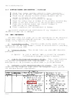
Signal Path Considerations. The path of the signal being
transmitted from the target area may change direction before being
received by your df antenna.
This can result in an erroneous line
of bearing reading.
Keep the following conditions in mind when
establishing a df site:
Radio waves can be reflected off buildings, mountains
or metal objects.
Position a direction finder set away
from such reflectors.
Metal objects, such as fences or armored vehicles, can
act as transmitters when some radio waves pass through
them.
Avoid metal objects that can cause reradiation.
Site vehicles should be in quadrant of least interest.
Radio waves can be bent as they pass from one atmospheric
condition to another.
This happens when signals pass
through the moist air over water
to the dry air over land.
D
O
not position a direction finder set near a shore line.
c.
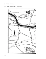
Tarqet Transmitter Location Considerations.
The location of
the target transmitter may contain conditions that will cause an
erroneous reading on your direction finder set.
You do not have
control over these conditions.
However, if the target transmitter
is more than 15 kilometers away, the chance of error is greatly
reduced.
2-19
Summary of Contents for AN/PRD-11
Page 2: ......
Page 6: ......
Page 10: ...TM 11 5825 278 12 2 RADIO RECEIVER DIRECTION FINDER SET AN PRD 11 1 0...
Page 18: ......
Page 21: ...1 13 LOCATION AND TM DESCRIPTION OF MAJOR COMPONENTS 11 5825 278 12 2 Continued 1 11...
Page 23: ...TM 11 5825 278 12 2 1 13 LOCATION AND DESCRIPTION OF MAJOR COMPONENTS Continued 1 13...
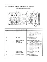
Page 32: ...TM 11 5825 278 12 2 2 2 RECEIVER CONTROLS INDICATORS AND CONNECTORS 2 2...
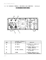
Page 33: ...TM 11 5825 278 12 2 2 2 RECEIVER CONTROLS INDICATORS AND CONNECTORS Continued 2 3...
Page 34: ...TM 11 5825 278 12 2 2 2 RECEIVER CONTROLS INDICATORS AND CONNECTORS Continued 2 4...
Page 35: ...TM 11 5825 278 12 2 2 2 RECEIVER CONTROLS INDICATORS AND CONNECTORS Continued 2 5...
Page 36: ...TM 11 5825 278 12 2 2 3 DF PROCESSOR CONTROLS INDICATORS AND CONNECTORS 2 6...
Page 37: ...TM 11 5825 278 12 2 2 3 DF PROCESSOR CONTROLS INDICATORS AND CONNECTORS Continued 2 7...
Page 38: ...TM 11 5825 278 12 2 2 3 DF PROCESSOR CONTROLS INDICATORS AND CONNECTORS Continued 2 8...
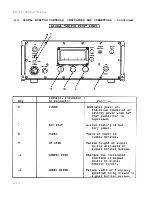
Page 39: ...TM 11 5825 278 12 2 2 4 SIGNAL MONITOR CONTROLS INDICATORS AND CONNECTORS 2 9...
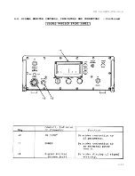
Page 40: ...TM 11 5825 278 12 2 2 4 SIGNAL MONITOR CONTROLS INDICATORS AND CONNECTORS Continued 2 10...
Page 41: ...TM 11 5825 278 12 2 2 4 SIGNAL MONITOR CONTROLS INDICATORS AND CONNECTORS Continued 2 11...
Page 42: ...TM 11 5825 278 12 2 2 5 ANTENNA CONNECTORS AND INDICATOR 2 12...
Page 46: ...TM 11 5825 278 12 2 2 9 SITE SELECTION Continued 2 16...
Page 48: ...TM 11 5825 278 12 2 2 9 SITE SELECTION Continued 2 18...
Page 100: ......
Page 107: ...TM 11 5825 278 12 2 2 11 INITIAL ADJUSTMENTS Continued GO ON TO SHEET 3 2 77...
Page 115: ...TM 11 5825 278 12 2 2 12 OPERATING PROCEDURES Continued GO ON TO SHEET 3 2 85...
Page 121: ...TM 11 5825 278 12 2 2 12 OPERATING PROCEDURES Continued 2 91...
Page 123: ...TM 11 5825 278 12 2 2 12 OPERATING PROCEDURES Continued 2 93...
Page 127: ...TM 11 5825 278 12 2 2 12 OPERATING PROCEDURES Continued 2 97...
Page 129: ...TM 11 5825 278 12 2 2 12 OPERATING PROCEDURES Continued GO ON TO SHEET 2 2 99...
Page 184: ......
Page 204: ...2 10 2 11a 4 11a TM 11 5825 278 12 2 4 9 TROUBLESHOOTING PROCEDURES Continued k 4 20...
Page 248: ...TM 11 5825 278 12 2 4 11 d MAINTENANCE PROCEDURES Continued 4 64...
Page 251: ...TM 11 5825 278 12 2 4 13 PACKING INSTRUCTIONS Continued 4 67...
Page 254: ......
Page 260: ...TM 11 5825 278 12 2 B 4 Section II MAINTENANCE ALLOCATION CHART...
Page 261: ...TM 11 5825 278 12 2 Section II MAINTENANCE ALLOCATION CHART Continued B 5...
Page 262: ...TM 11 5825 278 12 2 Section II MAINTENANCE ALLOCATION CHART Continued B 6...
Page 263: ...TM 11 5825 278 12 2 Section II MAINTENANCE ALLOCATION CHART Continued B 7...
Page 264: ...TM 11 5825 278 12 2 Section II MAINTENANCE ALLOCATION CHART Continued B 8...
Page 265: ...TM 11 5825 278 12 2 Section II MAINTENANCE ALLOCATION CHART Continued B 9...
Page 266: ...TM 11 5825 278 12 2 Section II MAINTENANCE ALLOCATION CHART Continued B 10...
Page 267: ...TM 11 5825 278 12 2 Section III TOOL AND TEST EQUIPMENT REQUIREMENTS B 11...
Page 268: ...TM 11 5825 278 12 2 Section III TOOL AND TEST EQUIPMENT REQUIREMENTS Continued B 12...
Page 269: ...TM 11 5825 278 12 2 Section IV REMARKS B 13...
Page 270: ...TM 11 5825 278 12 2 Section IV REMARKS Continued B 14...
Page 272: ...TM 11 5825 278 12 2 Section II COMPONENTS OF END ITEM AND BASIC ISSUE ITEMS LIST C 2...
Page 273: ...TM 11 5825 276 12 2 Section III BASIC ISSUE ITEMS C 3 C 4 blank...
Page 274: ...I...
Page 276: ...TM 11 5825 278 12 2 Section II ADDITIONAL AUTHORIZATION LIST D 2...
Page 278: ...TM 11 5825 278 12 2 Section II EXPENDABLE SUPPLIES AND MATERIALS LIST E 2...
Page 286: ......
Page 287: ......
Page 288: ......
Page 289: ......
Page 290: ......
Page 291: ......
Page 292: ......
Page 293: ......
Page 294: ......
Page 296: ......
Page 297: ......
Page 298: ...059582...


