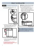
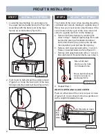


STEP 7
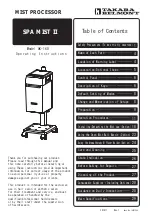
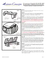
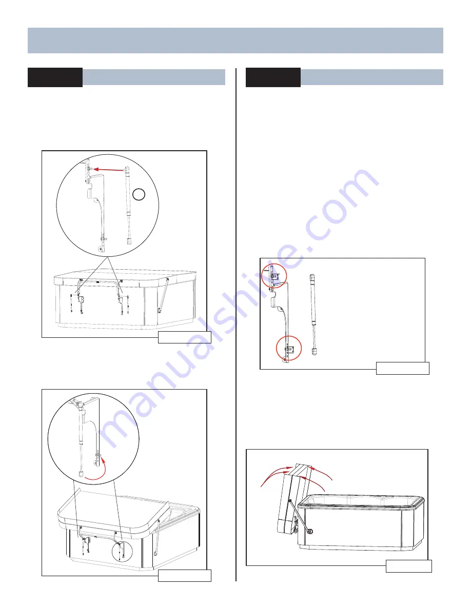
INSTALL GAS SPRING
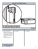
1. Locate the Gas Springs (C) and snap onto
the upper ball stud (attached to the Pivot Arm
Assembly) with the barrel end of the Gas
Spring up on both sides (Figure 8.1).
Figure 8.1
C
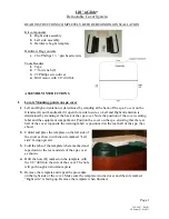
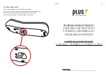
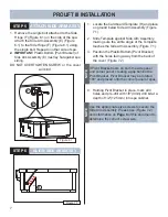
2. Fold Cover in half and pull to position shown
(Figure 8.2). Snap the lower joint of the Gas
Springs onto the lower ball stud (Figure 8.2).
Figure 8.2
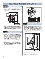
STEP 8
ADJUST GAS SPRING
The motion of the cover when opening should be
controlled and smooth rotating to a gentle stop. If
this is how your cover works, skip this step. If the
cover does not fully open or the cover does not
come to a gentle rest then do the following:
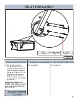
a. Remove both Gas Springs by reversing the
order in Step 7. Remove Gas Springs from each
ball stud by placing a fl at blade screwdriver
behind the retaining cup (hold up the clip with
the screwdriver) and pull Gas Spring away.
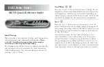
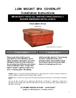
b. Remove both lower ball studs with a ½” wrench.
Raise or lower ball studs one hole (Figure 9.1)
c. Remove both upper ball studs with a ½” wrench.
Move ball studs in the same direction as in step b.
Move both ball
studs up one hole
to increase force
Move both ball studs
down one hole to
decrease force
Figure 9.1
d. Repeat Step 7
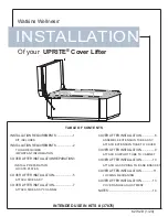
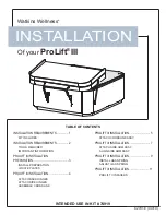
HOW TO OPEN AND CLOSE COVER
Push on either side of the cover to open or close
(Figure 9.2). Cover should come to a gentle rest
with a slight tilt towards the spa.
Figure 9.2
Push this side to open
Push
this
side to
close
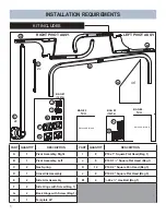
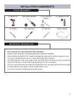
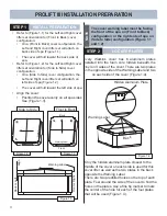
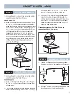
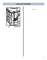
PROLIFT III INSTALLATION
9
Summary of Contents for ProLift III
Page 15: ...14 Figure 6 2 PROLIFT III SPACERS BLANK...
Page 16: ...62701 E 04 19...