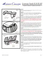


13
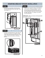
PIVOT BRACKET SPACER INSTALLATION
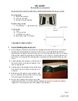
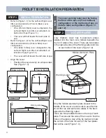
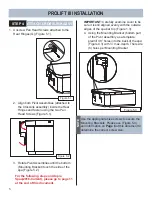
1. Locate the Template with 46° printed on it and
place on ground below Side Arm Assembly
(Figure 4.1).
2. Slide Template against Side Arm Assembly
making sure the entire angle of the Template
touches the Side Arm Assembly (Figure 4.1)
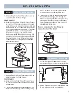
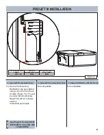
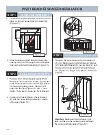
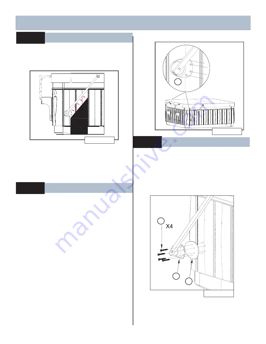
2. Position the Plastic Bottom (Pivot Bracket)
(E) with the holes facing toward the middle
of the spa (Figure 5.1).
1. Position W or X Side Spacer against Pivot
Bracket E, and insert two screws (L) from the
back. Then position arm so rib of side spacer
fi ts into appropriate groove. Predrill 7/64”
holes into the spa (Figure 5.1) with 1” max.
depth. There are (4) holes per Pivot Bracket.
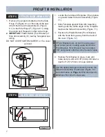
Important:
Make sure that the Spacer (W)
back end fi ts into the vertical groove between
the corner and side panel.(Figure 6.2)
46
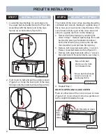
Figure 4.1
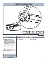
1. Remove the two screws (L) from the back of
W or X. Making sure that the holes on Spacer
(W) align with Bracket (E), secure bracket and
Spacer (W) to spa using 4 Flat head Screws
(L) (Figure 6.1). Bag # 3 (L) (#10 2” Flat Head
screws).
STEP 2
DRILL HOLES INTO SPA
STEP 3
SECURE PIVOT BRACKETS & SPACERS TO SPA
O
STEP 1
ALIGN SIDE ARM ASSY.
Figure 6.1
L
E
W
Figure 5.1
E
Summary of Contents for ProLift III
Page 15: ...14 Figure 6 2 PROLIFT III SPACERS BLANK...
Page 16: ...62701 E 04 19...