

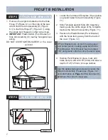


3
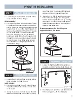
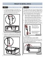
STEP 1
INSTALL PREPARATION
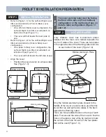
Figure 1.1
Front to Back
Warning Label
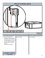
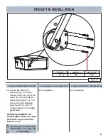
PROLIFT III INSTALLATION PREPARATION
Figure 1.3
Front or Right
Back or Left
Align
Warning Label
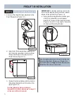
STEP 2
LOCATE PLATES
•
Refer to (Figure 1.1) for the Left and Right cover
lifter set orientation for (Front to Back) cover
confi guration:
•
On a (Front to Back) cover confi guration, the
Left and Right cover lifter set will attach on
back side of spa (Figure 1.1).
•
The cover will fold toward the back side of
spa.
•
Refer to (Figure 1.2) for the Left and Right cover
lifter set orientation for (Side to Side) cover
confi guration:
•
On a (Side to Side) cover confi guration, the
Left and Right cover lifter set will attach on
left side of spa (Figure 1.2).
•
The cover will fold toward the left side of spa.
Figure 1.2
• Align the cover:
• Position the cover evenly on all spa sides
See (Figure 1.3).
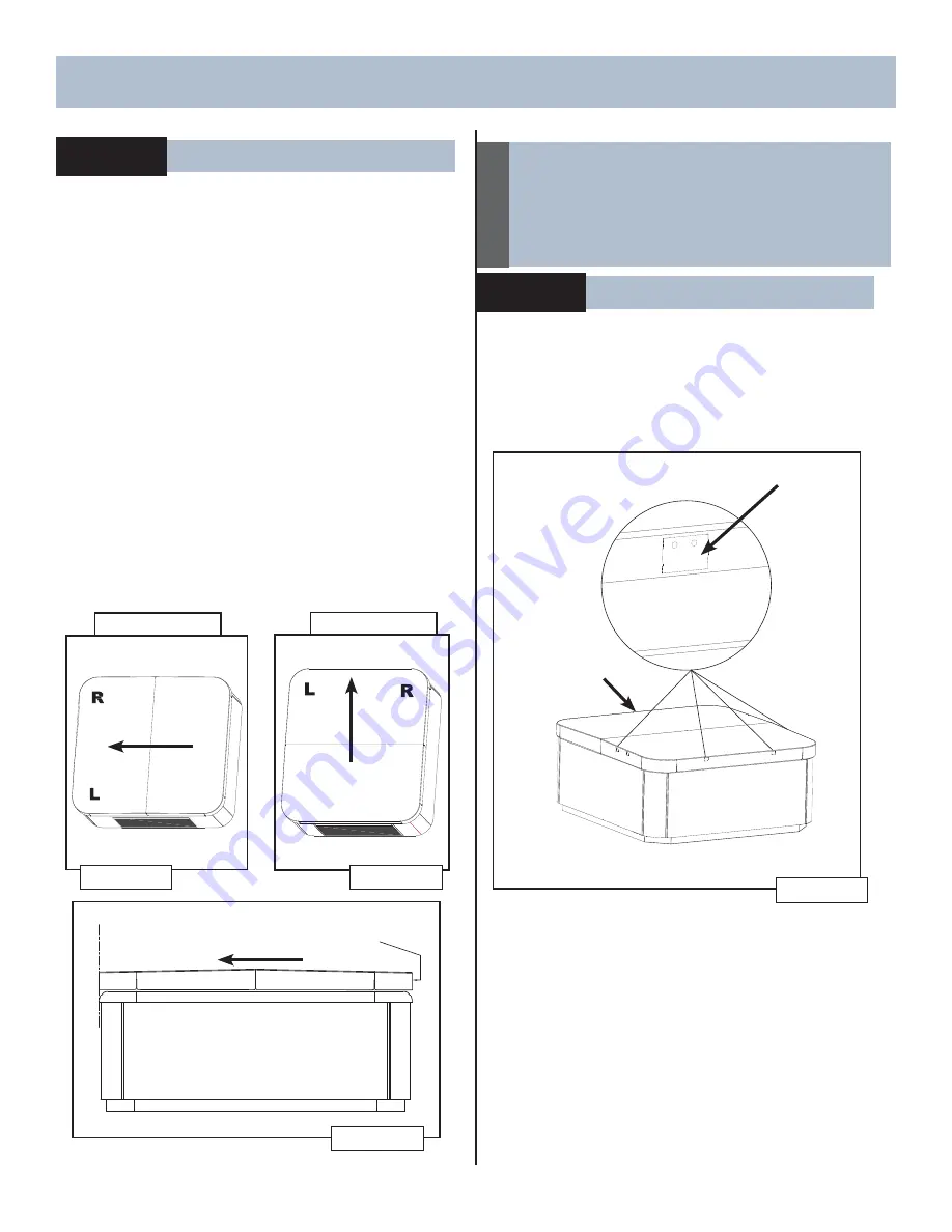
Figure 1.4
Warning Label
Hidden Aluminum Plate
Back
Side to Side
W
arning Label
The cover warning label must be facing
the front of the spa on (Front to Back)
confi guration or the right side of spa on
(Side to Side) confi guration (Figure 1.1
and 1.2)
NOTE
Back
Front
Every Watkins cover has 6 aluminum plates
installed into the foam core hidden beneath the
vinyl on 3 sides of the cover. There are two plates
on the opposite side of the Warning Label and two
on each side of the cover (Figure 1.4).
Only the hidden aluminum plate closest to the
middle of the cover on each side is used for this
cover lifter as well as the two plates in the back
opposite the Warning Label.
There are two predrilled holes on the top of each
plate. Feel around the side of the cover to fi nd the
holes in the plates. Use a fi ne tip marker to mark
the center of the hole for each of the four plates
that will be used (Figure 1.4).
Summary of Contents for ProLift III
Page 15: ...14 Figure 6 2 PROLIFT III SPACERS BLANK...
Page 16: ...62701 E 04 19...