

4
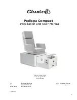
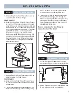
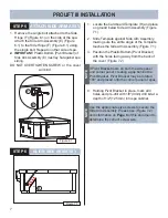
STEP 1
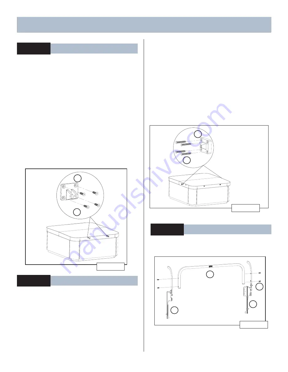
ATTACH BACK HINGES
1. Locate Bag #1, some of the contents will be
used to fasten the Rear Hinges.
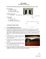
REAR HINGES:
2. Line up the top Rear Hinge(G) holes (Figure
2.1) with 2 of the marked holes on the back
side of the cover. Using the cordless drill and
square drive bit fasten the Rear Hinge(G) to
the cover by using two of the #10 x 1”square
(I) Flat Head screws on the top (marked)
holes fi rst. Using the 1/8” drill bit and the
bottom two holes of the Rear Hinge(G), drill
through the hidden aluminum plate followed
by inserting two more of the same screws
in the bottom holes. Repeat procedure for
second Rear Hinge.
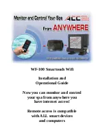
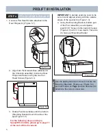
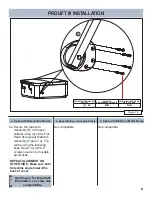
1. Locate Bag #1, some of the contents will be
used to fasten the Side Hinges.
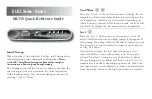
SIDE HINGES:
2. Line up the top Side Hinge(F) holes (Figure
2.2) with 2 of the marked holes on one side
of the cover.
3. Using the cordless drill and square drive bit
fasten the Side Hinge to the cover by using
two of the #10 x 1½”square (J) Flat Head
screws on the top (marked) holes fi rst.
4. Using the 1/8” drill bit and the bottom two
holes of the Side Hinge, drill through the
hidden aluminum plate followed by inserting
two more of the same screws in the bottom
holes. Repeat procedure for Side Hinge on
opposite side of the cover.
Repeat procedure for Side Hinge on
opposite side of the cover.
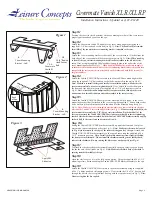
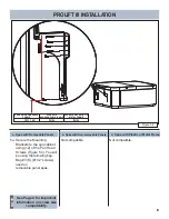
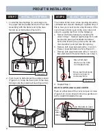
STEP 3
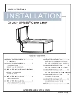
ASSEMBLE CROSSLINK
1. Locate the Right & Left Pivot Assemblies,
Crosslink and (4) ¼”-20 Hex Bolts (Figure 4.1).
Figure 4.1
A
C
4x
B
M
2. Orient (Figure 4.1) on fl oor and attach A and
B to C using (4) ¼”-20 Hex Bolts (M).
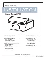
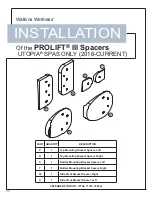
PROLIFT III INSTALLATION
Figure 2.1
G
I
4x
STEP 2
ATTACH SIDE HINGES
Figure 3.1
F
J
4x
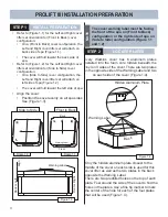
Summary of Contents for ProLift III
Page 15: ...14 Figure 6 2 PROLIFT III SPACERS BLANK...
Page 16: ...62701 E 04 19...