

5
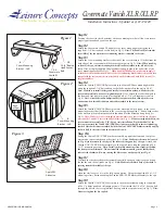
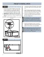
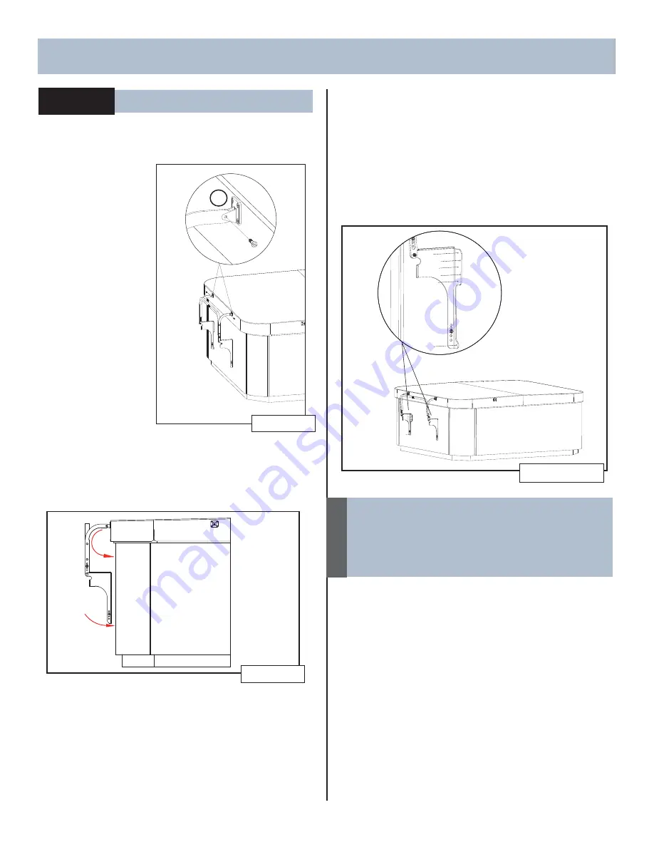
STEP 4 ATTACH CROSSLINK ASSY
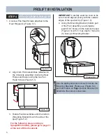
1. Unscrew Pan Head Screws attached to the
Rear Hinges (G) (Figure 5.1).
2. Align both Pivot Assemblies (attached to
the Crosslink assembly) inside the Rear
Hinges and fasten using the two Pan
Head Screws (Figure 5.1).
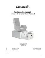
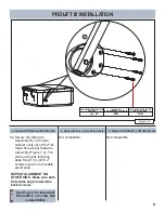
Figure 5.2
3. Rotate Pivot Assemblies until the bottom
(Mounting Bracket) touch the side of the
spa (Figure 5.2).
IMPORTANT:
Carefully examine cover to be
sure it is still aligned evenly with the outside
edges of the spa bar top (Figure 1.3).
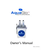
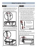
4. Using the Mounting Bracket (bottom part
of the Pivot Assembly as a template,
predrill 1/8” holes into the back of the spa
(Figure 4.3) with ½” max. depth. There are
(6) holes per Mounting Bracket.
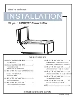
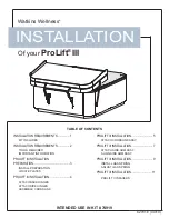
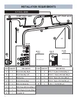
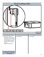
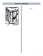
PROLIFT III INSTALLATION
Figure 5.3
For the following steps on Utopia
Spas(2016-Current), please go to page 11
at the end of this document.
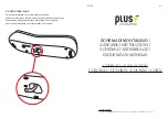
Use the appropriate size screws to secure the
Mounting Brackets. Please use (Figure 5.4)
and information on
Page 6
of this document to
determine the correct screw size.
NOTE
G
Figure 5.1
Summary of Contents for ProLift III
Page 15: ...14 Figure 6 2 PROLIFT III SPACERS BLANK...
Page 16: ...62701 E 04 19...