
6
6
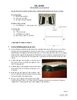
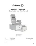
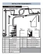
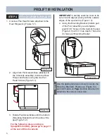
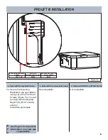
a. Spas with Removable Panels
c.
Spas with Plastic or Metal Frame
SPAS WITH REMOVABLE
PANELS
SPAS WITH
NON-REMOVABLE PANELS
N/A
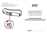
(K)
12X
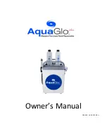
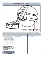
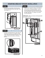
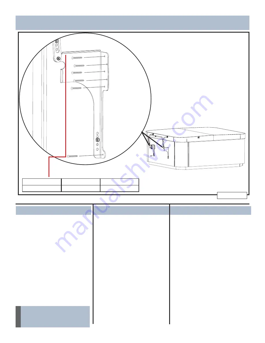
Figure 5.4
b. Spas with Non-removable Panels
SPAS WITH PLASTIC OR
METAL FRAME
N/A
See Page 2 for important
information on screw size
compatibility.
NOTE
1. Secure the Mounting
Brackets to the spa cabinet
using (12) of the Pan Head
Screws (Figure 5.4). You will
be using the following bag:
Bag #3 (K) (#10 2” screws)
used on
removable panel spas.
Not compatible.
Not compatible.
PROLIFT III INSTALLATION
a.
5
Summary of Contents for ProLift III
Page 15: ...14 Figure 6 2 PROLIFT III SPACERS BLANK...
Page 16: ...62701 E 04 19...