


7
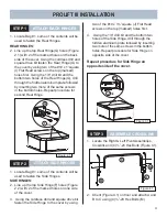
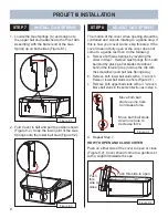
STEP 5
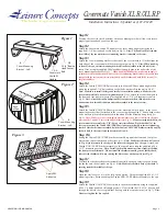
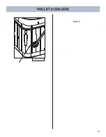
ATTACH SIDE ARM ASSY
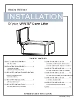
1. Remove the single bolt attached to the Side
Hinge (F)(Figure 6.1) on the side of the spa.
Attach the Side Arm Assembly (E) (Figure
6.1) to the Side Hinge (F) (Figure 6.1) using
the single bolt. Repeat on other side of spa.
2. IMPORTANT:
Plastic Bottom (Pivot Bracket) of
Side Arm Assembly (E) must lay fl at against spa
siding.
DO NOT OVERTIGHTEN SCREW or the cover
will bind.
F
Figure 6.1
E
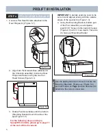
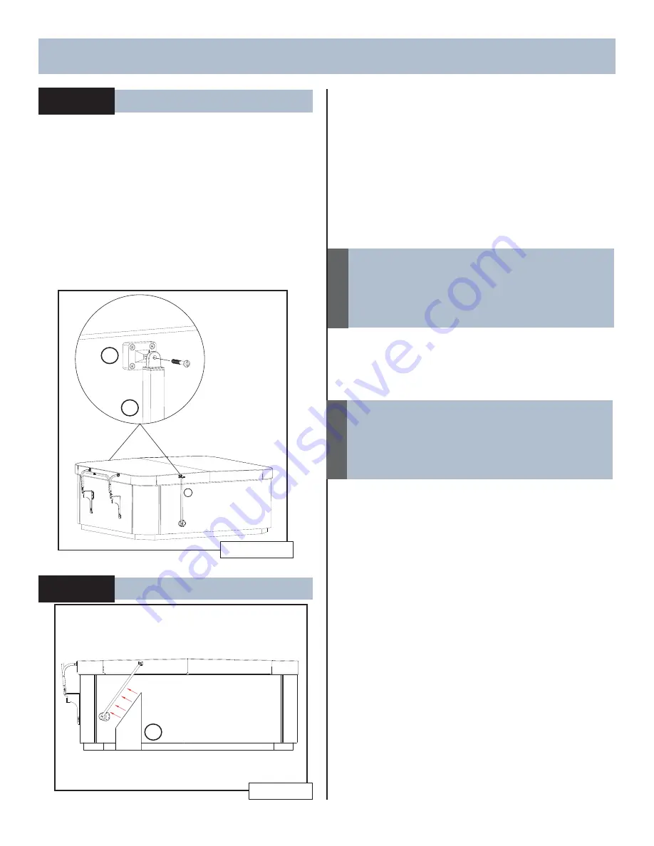
STEP 6
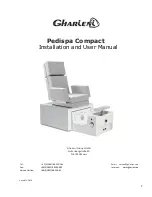
ALIGN SIDE ARM ASSY.
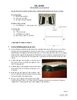
1. Locate the Cardboard Template (H) and place
on ground below Side Arm Assembly (Figure
7.1).
2. Slide Template against Side Arm Assembly,
making sure the entire angle of the Template
touches the Side Arm Assembly (Figure 7.1).
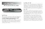
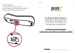
3. Position the Plastic Bottom (Pivot Bracket)
with the holes facing away from the back of
the cover (Figure 7.2).
4. Holding Pivot Bracket in place, mark all 4
holes and pre-drill with 1/8”(3mm) drill bit at a
depth of 1/2”(12.5mm) into spa cabinet.
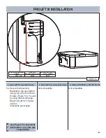
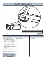
PROLIFT III INSTALLATION
E
Use the appropriate size screws to secure the
Side Arm Assembly. Please use (Figure 7.2)
and information on
Page 8
of this document to
determine the correct screw size.
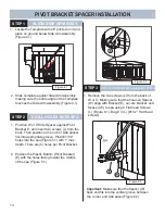
NOTE
If Pivot Bracket rests on both the side panel
and corner panel, creating a gap behind the
Pivot Bracket, Pivot Bracket may be rotated
180° and placed onto the corner panel of spas.
NOTE
Figure 7.1
H
46˚
Summary of Contents for ProLift III
Page 15: ...14 Figure 6 2 PROLIFT III SPACERS BLANK...
Page 16: ...62701 E 04 19...