


11
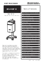
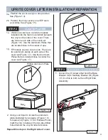
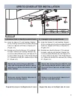
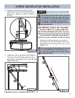
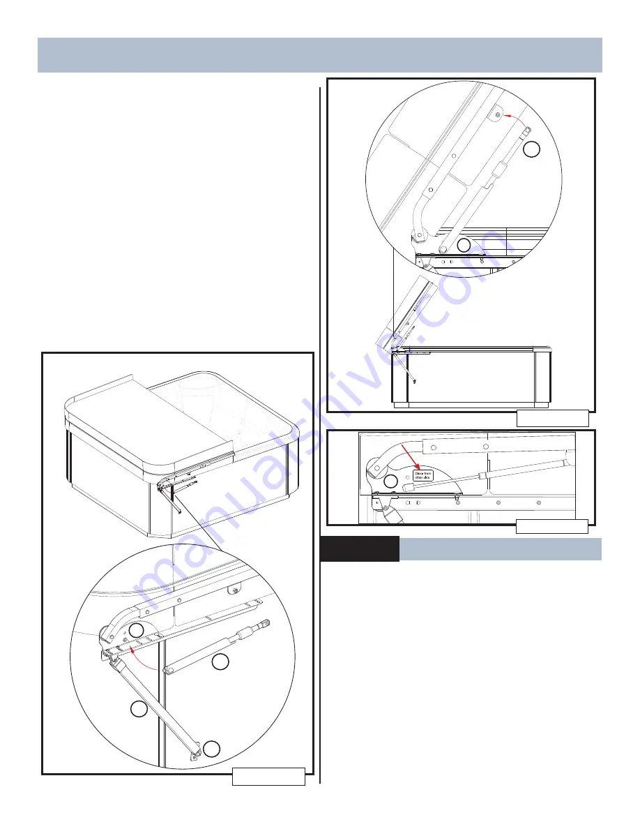
2. With the cover closed, snap the Gas Spring
Lock end of the Gas Spring onto the lower ball
stud (which is on the Base Bracket (A)
(Figure 7.2).
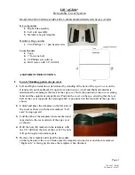
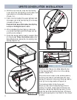
3. Open Cover and align the upper ball stud with
the larger end of the Gas Spring (F) and snap
into place (Figure 7.3).
Repeat these steps(Excluding Gas Spring
Lock) on the Right side of cover.
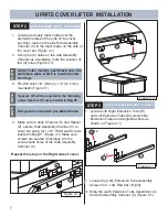
4. When installing the Gas Spring, make sure
you install Gas Spring with the larger end up
and the rod end down.
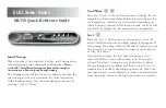
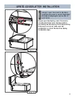
5. Place the orange sticker label( Located in Bag
#1) that reads “
Close from other side
”on the
Base Bracket (A), above the non-locking Gas
Spring (Figure 7.4).
Figure 7.2
F
H
B
A
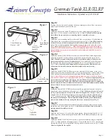
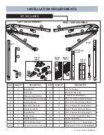
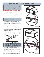
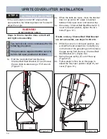
STEP 7
LOCKING MECHANISM
The Sure lock Sleeve (L) slides along the top
of the Gas Spring (F) when it is in free-sliding
position (Figure 8.1)
When the cover is open in the vertical position,
the Sure-Lock Sleeve will slide down the Gas
Spring (F) and rest on the top of the Gas Spring
Lock (I) in a locking position (Figure 8.2).
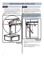
The locking position of the Sure-Lock
Sleeve (L) prevents the Gas Spring (F) from
closing. To unlock, simply raise the Sure-Lock
Sleeve (L) abode the Gas Spring Lock (I), and
push the top of the Gas Spring Lock (I) forward
while gently easing the cover down to the closed
position.
Figure 7.3
F
A
UPRITE COVER LIFTER INSTALLATION
Figure 7.4
A
Summary of Contents for UPRITE
Page 15: ...14 NOTES ...
Page 16: ...62732 D 01 20 ...