Electrical Requirements
115-230 VOLT CONVERTIBLE MODELS
• Sovereign
®
(Model I)
• Prodigy
®
(Model H)
• Jetsetter
®
(Model J & JJ)
230 VOLT CONVERSION INSTRUCTIONS
Refer to the following instructions to convert a 115 volt spa to a 230 volt spa.
N
NO
OT
TE
E:: Converting the spa to 230 volt operation should only be done by an
authorized service agent or a qualified electrician.
Required Parts: (3) P.N. 36021 program jumpers (staged on JP jumpers in IQ 2020
™
control box) and (1) P.N. 20679 or 37087 subpanel (230 volt)
1. Disconnect the power cord from the house receptacle.
2. Remove the screws and open the equipment compartment door.
3. Remove the screws on the front of the IQ 2020 spa control box.
4. Open the control box cover.
5. Identify TB-1, located in the lower left-hand corner inside the control box.
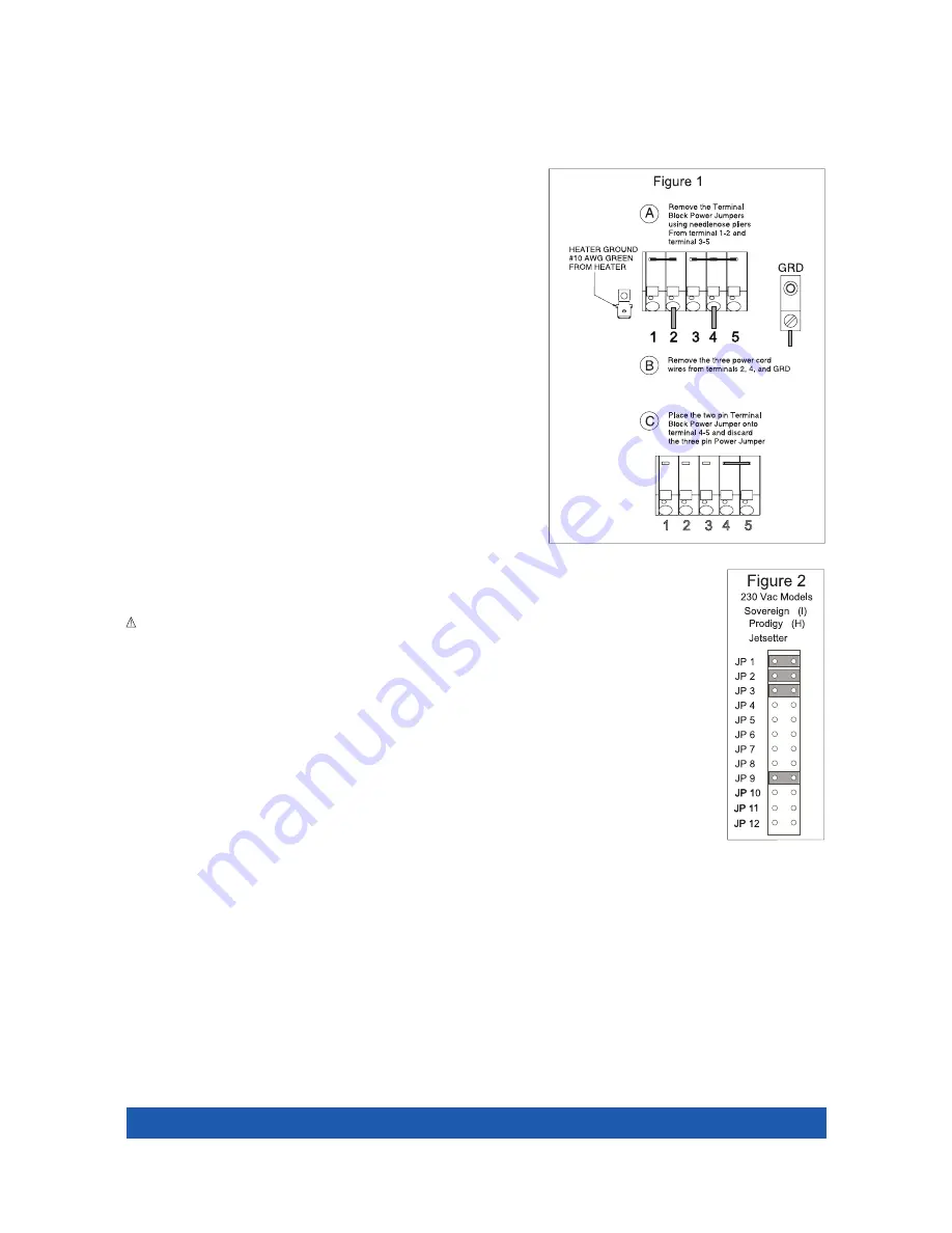
6. Refer to Figure 1, item A. Remove both the 3 pin jumper attached to terminals 3,
4, and 5, and the 2 pin jumper attached to terminals 1 and 2.
7. Refer to Figure 1, item B. Remove the power cord wires from terminals 2, 4 and
the system ground terminal.
8. Refer to Figure 1, item C. Attach the 2 pin jumper to terminals 4 and 5.
9. Unscrew the power cord strain relief and remove the power cord from the
access hole in the control box.
10. On the large circuit board, locate the program jumpers, JP-1 through JP-12 (positioned near the center of the circuit
board, with JP-1 being the top jumper).
W
WA
AR
RN
NIIN
NG
G:: Do not allow pliers to contact any electronic components inside the control box.
11. Use a pair of needlenose pliers to place the program jumpers as shown in Figure 2 (use Watkins P.N. 36021).
N
NO
OT
TE
E:: The program jumpers JP-1, JP-2 and JP-3 must be set correctly for the spa to operate. Figure 2 illustrates the
correct jumper settings.
Converting from 115 volts to 230 volts changes the voltage supplied to the heater from 115 volts to 230 volts. The jet
pump will continue to operate at 115 volts.
INSTALLATION INSTRUCTIONS
1. To connect the electrical service, first remove the screws from the equipment compartment door. Carefully pull the
door panel away and remove it from the spa.
2. Locate the IQ 2020 spa control box. Loosen the screws on the front of the control box. Remove the screws and the
control box cover.
3. Route the electrical service from the subpanel into the spa equipment compartment. Position the conduit in the
recess provided between the frame and the door.
N
NO
OT
TE
E:: The subpanel must be placed in sight of the spa, at a minimum distance of 5 feet away.
4. Connect the supply conduit to the bottom of the IQ 2020 spa control box, using a minimum of 3/4” liquid-tight, flex conduit fittings.
WIRING CONNECTIONS
1. Identify the TB-1 terminal block, located at the lower left-hand corner of the control box.
2. Connect the #12 AWG, BLUE wire from the subpanel 20 amp breaker, terminal L1 to TB-1 terminal 2.
3. Connect the #12 AWG, WHITE wire from the subpanel 20 amp breaker, terminal N (load neutral) to TB-1, terminal 5.
N
NO
OT
TE
E:: The WHITE neutral wire must be attached to the load neutral on the 115 volt, 20 amp breaker (not the neutral bus bar in the subpanel). The
WHITE pigtail (neutral) wire from the 20 amp breaker is already connected to the neutral bus bar.
Page 26
(J/JJ)
Electrical Requirements
Summary of Contents for Hot Spring
Page 1: ...Owner sManual...


