background image

P2T 2-Knife Trimmer

Page 1-10

CHAPTER 1 - Before Installation

Issue 1b, June 2018

P2T Installation Hardware

1.7.3

PBS/P2T Pivot Bracket. Information.

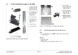
When the P2T is used with a PBS, the PBS/P2T pivot bracket is used instead of 
the docking pivot pin supplied with the PBS. See 

Figure 1:9.

The PBS/P2T pivot bracket is supplied in:

940-180 KIT, PBS+P2T MISC CONFIGURATION PARTS or the

072-32x KIT, PBS/P2T TRIMMINGS CONVEYOR

Fitting instructions are supplied in the PBS Unpacking and Installation Instructions.

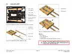
PBS/P2T pivot bracket

Pivot post

M8x35 cap-head screw

Figure 1:9. PBS/P2T pivot bracket

Summary of Contents for P2T

Page 1: ...P2T 2 Knife Trimmer Unpacking and Installation Instructions Issue 1b June 2018 969 359...

Page 2: ...document is subject to change without notice Watkiss Automation Limited makes no warranty of any kind with regard to this material includ ing but not limited to the implied warranties of merchantabil...

Page 3: ...3 Prepare the BLM 3 1 Remove Covers from the BLM 3 2 3 2 Remove the Outfeed Stacker from the BLM 3 4 3 3 Fit the Installation Hardware to the BLM 3 5 4 P2T Installation 4 1 Fit the P2T to the BLM 4 2...

Page 4: ...P2T 2 Knife Trimmer Page 1 2 Issue 1b June 2018...

Page 5: ...for Installation 1 8 1 6 1 The Location of the Supplied Tools in the BLM 1 8 1 6 2 The Location of the Supplied Tools in the P2T 1 8 1 7 P2T Installation Hardware 1 9 1 7 1 Supplied with the P2T 2 Kn...

Page 6: ...o prevent injury you must follow the instructions Caution A CAUTION message tells you that a procedure or operation can damage the machine or the product To prevent damage you must follow the instruct...

Page 7: ...kground On the outside of the mains input panel next to the mains input socket 500 009 Safety Earth White figure on a green background On the inside of the mains input panel 500 254 Earth continuity W...

Page 8: ...t altitudes not more than 2000m above sea level 2000m Black figure on a silver background On the serial number label Outside of the machine near to the mains power inlet Use only in non tropical condi...

Page 9: ...00 kg 660 lb The shipping weight of the P2T is 360 kg 792 lb You can lift the P2T directly with a fork lift or pallet truck but where possible lift the pallet and P2T together If you lift the P2T dire...

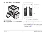
Page 10: ...5 mm 147 inches and a minimum width of 1100 mm 43 inches See Figure 1 3 Figure 1 3 The space needed to unload the P2T 1 5 2 Space to Install the P2T 1 5 2 1 PowerSquare and P2T 2 Knife Trimmer Left to...

Page 11: ...Space Needed to Install the P2T 1 5 2 2 PowerSquare and P2T 2 Knife Trimmer Right to Left BLM600 Connecting Bridge P2T Trimmer Input for Mains Power Supply Input for Mains Power Supply Maintenance are...

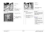
Page 12: ...Pen or pencil Wheel gauge tool supplied with the P2T See Section 1 6 2 1 6 1 The Location of the Supplied Tools in the BLM Figure 1 4 Location of the supplied tools in the BLM The ratchet handle 14 mm...

Page 13: ...erface Kit for BLM Figure 1 8 P2T PBS Interface Kit for BLM Supplied with the BLM600 Note If there is a PBS serial number WA PBS 0060 or later already installed then you do not need an additional inte...

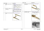
Page 14: ...ot bracket is used instead of the docking pivot pin supplied with the PBS See Figure 1 9 The PBS P2T pivot bracket is supplied in 940 180 KIT PBS P2T MISC CONFIGURATION PARTS or the 072 32x KIT PBS P2...

Page 15: ...t on serial number can need modification Fit the modifications as shown below BLM Serial No WA PSQ 0800 onward Modification is not needed BLM Serial No WA PSQ 0500 0799 940 161 KIT PSQ MOD 61 UPDATES...

Page 16: ...machine covers some of which are removed in installation procedures Figure 1 10 Machine covers_1 TABLE 1 2 Machine covers_1 Cover Description Top cover LH side cover Note These 2 covers are not inter...

Page 17: ...P2T 2 Knife Trimmer Page 2 1 CHAPTER 2 Unpack the P2T Issue 1b June 2018 CHAPTER 2 Unpack the P2T 2 1 Remove the Covers from the P2T 2 2 2 2 Unload the P2T 2 5...

Page 18: ...you do not damage the paintwork Caution Keep all of the packaging material To prevent damage to the P2T when shipped you must use the correct packaging material Caution When you remove the covers fro...

Page 19: ...n 1 Remove the outer packaging material from the P2T Keep all of the packaging materials To prevent damage to the P2T when shipped you must use the correct packaging materials 2 Remove the plastic wra...

Page 20: ...rial for the P2T Cut and discard the cable ties that hold the castors in position 5 Adjust the castors to the correct height to unload the P2T from the pallet See Figure 2 4 To unload the P2T from the...

Page 21: ...shown Tools 8mm Allen key 2 x 17 mm spanners 17 mm socket Ratchet handle supplied with the BLM See Section 1 6 1 Ramp brace Needs 8mm Allen key Upper ramp Retaining bolt Lower ramp Metal channel Cut...

Page 22: ...e 2 6 and Figure 2 7 The M6x90 bolts are located in the pal let in the cut outs that locate the upper ramps You will need the M6x90 bolts to lock the upper ramps to the pallet in a later step 3 Fit th...

Page 23: ...ansit brackets 8 IMPORTANT Rotate the bracket assem blies to the side and away from the P2T Remove the retaining bolts from the ramp end of the bracket assemblies See A in Figure 2 8 Rotate the bracke...

Page 24: ...P2T 2 Knife Trimmer Page 2 8 CHAPTER 2 Unpack the P2T Issue 1b June 2018 Unload the P2T...

Page 25: ...rom the BLM 3 4 3 3 Fit the Installation Hardware to the BLM 3 5 3 3 1 Fit the Mounting Brackets and Outfeed Covers 3 5 IMPORTANT Make sure you have read Section 1 7 P2T Installation Hardware and Sec...

Page 26: ...r Drive cover screw Outfeed top cover fixing screws Drive cover Outfeed top cover Figure 3 2 Remove the outfeed top cover RH top short cover Fixing screw Fixing screw Drive cover screw Figure 3 3 Remo...

Page 27: ...1 drive cover screw on each side of the machine Close the folder cover Lift the drive cover approximately 15 mm Disengage the drive cover from the support brackets Pull the cover toward you 7 Left to...

Page 28: ...he outfeed stacker outward until the bottom of the outfeed mounting plate is away from the bottom chassis rail 4 Lower the outfeed stacker to disengage the top of the outfeed mounting plate from behin...

Page 29: ...T pivot kit included with the P2T 1 Pivot post with M5x40 cap head screw M5 nyloc nut and 2 x M5 washers 12 5mm O D 2 Pivot location bracket with 2 x M5x12 cap head screws and spring washers 3 Pivot c...

Page 30: ...shakeproof washers Figure 3 10 Fit the mains power cable to the lower chassis rail Left to Right machine shown Large cable ties Mains power cable Leave approximately 300 mm free cable for connection t...

Page 31: ...racket Figure 3 14 Pivot bracket item fitted to the P2T Mains power input P2T Pivot bracket Step Action Information 1 Fit the docking latch assembly to the BLM outfeed book support Item Figure 3 8 The...

Page 32: ...sure you leave approximately 300 mm of cable to the front of the BLM to connect to the mains input of the P2T Fit a cable tie either side of the outfeed and one to the rear of the bridge docking plate...

Page 33: ...amp bracket to the BLM Item and item Figure 3 7 Remove the M5 screws and washers to separate items and Fit the pivot location bracket to the front of the lower chassis rail of the BLM then slide to th...

Page 34: ...P2T 2 Knife Trimmer Page 3 10 CHAPTER 3 Prepare the BLM Issue 1b June 2018 Fit the Installation Hardware to the BLM...

Page 35: ...ne 2018 CHAPTER 4 P2T Installation 4 1 Fit the P2T to the BLM 4 2 4 2 Alignment of the P2T to the BLM 4 7 4 3 Fit the Covers to the P2T and to the BLM 4 9 4 3 1 Check and Adjust Stacker Mounting Heigh...

Page 36: ...easure Spirit level 14 mm socket supplied with the BLM See Section 1 6 1 Ratchet handle supplied with the BLM See Section 1 6 1 Masking tape Pen or pencil Torch or similar light source Figure 4 1 Cast...

Page 37: ...P2T top cover Outfeed cover Figure 4 5 BLM outfeed cover height The distance between the top of the outfeed cover and the floor Infeed conveyor support See Figure 4 7 Figure 4 6 P2T infeed height The...

Page 38: ...and spring washers 3 Pivot clamp bracket 4 Pivot bracket with 2 x M5x12 cap head screws and spring washers 5 3 x long cable ties 6 3 x short cable ties Figure 4 9 Adjustment holes Pivot location brac...

Page 39: ...the 4 adjustable castors to adjust the height of the P2T To prevent twist on the frame of the P2T adjust each adjustable castor a maximum of 6 mm 0 25 inch in turn The threads of the adjustable casto...

Page 40: ...outfeed conveyor support just clears the 4 mm Allen key then the height of the P2T is correct If the 4 mm Allen key is pushed out of position then the P2T is too low Raise the P2T Step Action Informat...

Page 41: ...feed cover Step Action Information 1 Connect the P2T to the mains power Important If you are installing a P2TT auxiliary transformer then set the correct voltage for the auxiliary transformer See Sect...

Page 42: ...to the end of the outfeed cover The measurements must be the same If the measurements are different then use a different hole in the pivot location bracket to move the P2T in the needed direction The...

Page 43: ...hine covers LH side cover Top cover RH side cover Trim bin Fitted to the RHS for Left to Right machines Fitted to the LHS for Right to Left machines Outfeed stacker Top cover open Figure 4 18 Fit a si...

Page 44: ...P2T 3 Fit the covers to the BLM See Figure 4 19 Fit the outfeed cover RH The outfeed cover RH is held in position by 1 x button head screw Fit the outfeed cover LH The outfeed cover LH is held in posi...

Page 45: ...pin A Loosen the orange handscrew Engage the stacker collect table with the outfeed stacker Step Action Information A Fit the safety pin Slide the stacker collect table to the correct position for th...

Page 46: ...panel of the trim bin is in the lowest position Loosen the screws at the 2 sides as necessary Put the trim bin below the trimmings outfeed Raise the back panel of the trim bin until the back panel to...

Page 47: ...he low position then go to the next step 2 Disconnect the power cable from the main body of the P2T The power cable is beneath the outfeed stacker Press the catch A and pull the plug Do not pull the c...

Page 48: ...rs to the P2T and to the BLM 4 Engage the lower set of keyhole slots with the fixing studs on the trimmer See Figure 4 24 Lift the stacker approximately 25mm and push onto the fixing studs Lower the s...

Page 49: ...35 cap head screw Figure 4 25 PBS P2T pivot bracket Figure 4 26 Fit the PBS P2T pivot bracket From below Wheel mount plate on the BLM LH front PBS P2T pivot bracket LH front castor on the BLM Figure 4...

Page 50: ...t plate See Figure 4 26 and Figure 4 27 Make sure that the holes in the PBS P2T pivot bracket align to the hole in the wheel mount plate 3 Fit the M8x35 cap head screw See Figure 4 27 and Figure 4 28...

Page 51: ...1b June 2018 Fit the PBS P2T Pivot Bracket to the BLM 8 Insert the pivot post through the hole in the PBS P2T pivot bracket 9 Use the cap head screw washers and nut to fasten the pivot post to the PB...

Page 52: ...P2T 2 Knife Trimmer Page 4 18 CHAPTER 4 P2T Installation Issue 1b June 2018 Fit the PBS P2T Pivot Bracket to the BLM...

Page 53: ...P2T 2 Knife Trimmer Page A 1 APPENDIX A Miscellaneous Issue 1b June 2018 APPENDIX A Miscellaneous A 1 Check and Adjust the P2T for Level A 2 A 2 Remove the LH Bottom Large Cover A 4...

Page 54: ...ivot bracket Bubble position Indication Action The bubble is in the win dow This indicates the machine is level This is correct Action is not needed The bubble is too far to the left and not inside th...

Page 55: ...2mm Caution Do not adjust the adjustable castors further than the top of their threads See Figure A 3 2 Check the P2T for side to side level on the top cover Compare to TABLE A 1 If necessary adjust...

Page 56: ...Figure A 5 Cover lifted LH bottom large cover Step Action Information 1 Lift the LH bottom large cover upwards as far as possible See Figure A 4 and Figure A 5 Make sure the brackets at the top of the...

Page 57: ...T B 1 Disconnect the P2T from the BLM B 2 B 2 Prepare the P2T B 4 B 3 Prepare the Pallet B 6 B 4 Load the P2T onto the Pallet B 9 B 5 Remove the Installation Hardware from the BLM B 12 B 5 1 Remove Co...

Page 58: ...atchet handle supplied with the BLM See Section 1 6 1 Mains power cable Mains power socket Mains on off switch Fuse holders Figure B 1 P2T mains power input B Figure B 2 Fold the outfeed stacker A Ste...

Page 59: ...pres sure and the outfeed stacker will automatically fold 4 Rotate the P2T away from the BLM 5 Disconnect the mains power cable from the P2T See Figure B 1 Disconnect the mains power cable from the m...

Page 60: ...ction 1 6 1 14mm socket supplied with the BLM See Section 1 6 1 Ratchet handle supplied with the BLM See Section 1 6 1 Figure B 5 Remove the stacker collect table Stacker collect table Figure B 6 Pivo...

Page 61: ...achine to prevent damage 3 Remove the pivot bracket See Figure B 6 2 screws hold the pivot bracket to the bottom of the P2T 4 Remove the LH side cover and the RH side cover See Figure B 7 and Figure B...

Page 62: ...with the BLM See Section 1 6 1 Figure B 10 Ramps and ramp brace stored on the pallet P2T not shown Ramp brace Needs 8mm Allen key Upper ramp Retaining bolt Lower ramp Metal channel Cut out to locate...

Page 63: ...re B 10 and Figure B 11 The M6x90 bolts are located in the pallet in the cut outs that locate the upper ramps You will need the M6x90 bolts to lock the upper ramps to the pallet in a later step 3 Fit...

Page 64: ...Turn the screw to the right until the lift bracket is at the highest point Turn the screw to the left one half turn 7 Rotate the bracket assemblies to the side Remove the retaining bolts from the ramp...

Page 65: ...7mm socket Ratchet handle supplied with the BLM See Section 1 6 1 Warning The installed weight of the P2T 2 Knife Trimmer is 300kg 660lb You must follow good Health and Safety procedures when you lift...

Page 66: ...up the ramps and onto the pallet See Figure B 13 When the P2T is far enough onto the pallet you will feel the castors engage with a recess in the metal channel 3 Rotate the bracket assemblies inward R...

Page 67: ...er packing Adjust the height of the castors as needed 9 Use cable ties to lock the castors in position 10 Fit the side covers to the P2T 11 Fit the trim bin on the pallet against the LH side cover See...

Page 68: ...eft to Right machine shown Folder cover Drive cover Outfeed cover top Outfeed cover RH Outfeed cover LH Outfeed book support Folder cover Drive cover screw Outfeed top cover fixing screws Drive cover...

Page 69: ...ee Figure B 18 and Figure B 19 and Figure B 20 Remove the RH top short cover The RH top short cover is held in position by 2 x button head screws Remove the 2 drive cover screws There is 1 drive cover...

Page 70: ...unting bracket Figure B 23 Mains power cable fitted to the lower chassis rail L to R machine Large cable ties Mains power cable Location of the pivot clamp bracket and pivot location bracket Outfeed b...

Page 71: ...Remove the outfeed cover Remove the 2 x M5x10 button head screws that fasten the top edge of the outfeed cover to the cover mounting bracket Lift the outfeed cover and pull toward you 2 Disconnect th...

Page 72: ...e toward you 6 Remove the docking latch assembly See Figure B 24 The docking latch assembly is held in position by 2 x M5x12 cap head screws with shakeproof washers Step Action Information 7 Remove th...

Page 73: ...ws 4 Left to Right Machines Only For online machines fit the cover assembly link rear to the connecting bridge See Figure B 21 Figure B 27 BLM covers Left to Right machine shown Folder cover Drive cov...

Page 74: ...P2T 2 Knife Trimmer Page B 18 APPENDIX B Uninstall the P2T Issue 1b June 2018 Remove the Installation Hardware from the BLM...

Page 75: ...Trimmer Page C 1 APPENDIX C Adjust the Transformer Issue 1b June 2018 APPENDIX C Adjust the Transformer C 1 Adjust the Operating Voltage C 2 C 1 1 Preparation C 3 C 1 2 Adjust the Voltage C 4 C 1 3 Co...

Page 76: ...tch Mains power input fuses Mains power input connector Voltage warning label Output voltage label Mains power output connector Top cover Figure C 1 P2TT Auxiliary transformer Figure C 2 Inside the au...

Page 77: ...Voltage Tappings Figure C 4 Transformer tappings Step Action Information 1 Remove the top cover from the P2TT auxiliary transformer See Figure C 1 The top cover of the P2TT auxiliary transformer is he...

Page 78: ...eg on the selected tap location 5 Insert the bare end of the brown wire into the open terminal 6 Release the white peg This action closes the terminal jaws 7 Make sure the brown wire is held correctly...

Page 79: ...Transformer Issue 1b June 2018 Adjust the Operating Voltage 4 Connect the mains power cable supplied with the P2T to the wall outlet 5 Use the mains power on and off switch to turn on the auxiliary t...

Page 80: ...P2T 2 Knife Trimmer Page C 6 APPENDIX C Adjust the Transformer Issue 1b June 2018 Adjust the Operating Voltage...

Page 81: ...tallation Hardware to the BLM Chapter 4 Amended Section 4 1 Fit the P2T to the BLM Amended Section 4 2 Alignment of the P2T to the BLM Amended Section 4 3 Fit the Covers to the P2T and to the BLM Appe...

Page 82: ...P2T 2 Knife Trimmer Page D 2 APPENDIX D List of Changes Issue 1b June 2018...

Page 83: ......

Page 84: ...Watkiss Automation Limited 1 Blaydon Road Middlefield Industrial Estate Sandy Bedfordshire SG19 1RZ United Kingdom Tel 44 0 1767 685700 Fax 44 0 1767 689900 Email info watkiss com...

Reviews: