2
WATLOW Series 733/734 Service Manual
Install & Wire, Chapter 1
This manual is a supplement to the Series 733/734 Program Manual. It is for
configuring, servicing and calibrating your control. Use this manual in conjunc-
tion with the Series 733/734 Program Manual and Data Communications manual.
Contents
Technical Assistance
If you encounter a problem with your Series 733/734
control, review all of your configuration information to
verify that your selections are consistent with your
application... Inputs, Outputs, Alarms, Limits, etc. If the
problem persists after checking the above, you can get
technical assistance by dialing:
1-507-454-5300
An Application Engineer will discuss your problem with
you. Please have the following information available:
•
Complete model number
• Revision number
•
All configuration information
• User's manual
The model and serial numbers can be found on the
outside of the case.
Your Feedback
Your comments or suggestions on the manual are
welcome, please send them to: Technical Writer, Watlow
Controls, 1241 Bundy Blvd., P.O. Box 5580, Winona, MN
55987-5580, or phone 507/454-5300. The Watlow Series
733/734 Service Manual and integral software are
copyrighted by Watlow Winona, Inc., © 1995, with all
rights reserved.
Page Item
Chapter 1
3
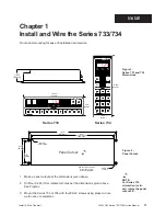
Install and Wire the Series 733/734
3
Dimensions
3
Panel Cutout
4
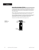
How to Wire the Series 733/734
5
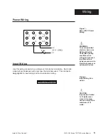
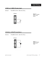
Power Wiring
5
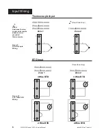
Input Wiring
8
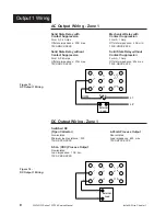
Output 1 Wiring
9
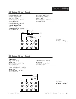
Output 2 Wiring
10
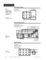
Event Input Wiring
10
Event Output Wiring
10
Alarm Wiring
11
System Wiring Examples
Chapter 2
12
The Setup Mode
12
Advancing Through the Setup Mode
12
Select or Change Setup Data Within the Mode
13
Setup Parameters
16
Setup ModeTable
Notes
˜
Informational notes alert you to important details.
When you see a note icon, look for an explanation in
the margin.
Safety Information
Boldface safety information protects both you and
your equipment. Please be attentive to them. Here
are explanations:
ç
The CAUTION symbol (exclamation point) in the wide
text column alerts you to a "CAUTION," a safety or
functional hazard which could affect
your equipment or
its performance. A full explanation is in the narrow
column on the outside of the page.
∫
The WARNING symbol (lightning bolt) in the wide text
column alerts you to a "WARNING," a safety hazard
which could affect
you and the equipment. A full
explanation is in the narrow column on the outside of
the page.
Chapter 3
16
The Service Mode
17
Service Parameters
18
Service Mode Table
Chapter 4
20
Auto-Tuning
21
Manual Tuning
Chapter 5
22
The Calibration Mode
23
Calibration Parameters
24
Calibration Procedures
Appendix
30
Glossary
32
Index
33
Warranty/Returns
34
Specifications
35
Ordering Information
36
CE Declaration of Conformity
37
Notes
38
Notes


