2 4
Watlow Series 935A User’s Manual
Configuration Menu
[``In]
Input Type
[`C_F]
Celsius/Fahrenheit
[``rL]
Input Range Low
[``rh]
Input Range High
[`Ot1]
Output 1 Function
[`Ot2]
Output 2 Function
[dISP]
Display Default
[ALtY]
✓
Alarm Type
[AhYS]
✓
Alarm Hysteresis
[`LAt]
✓
Alarm Latch
[`SIL]
✓
Alarm Silencing
[FAIL]
Failure Mode
Operations
Menu
[`Aut]
Auto-tune
[`ALO]
✓
Alarm Range Low
[`AhI]
✓
Alarm Range High
[`Pid]
PID
[CnFG]
Configuration
Learning Alarms
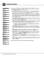
Alarms signal an excursion from normal operating conditions. In general, audible alarms or lights
connected to alarm outputs will signal a problem. In the 935A the front panel LED “1” or “2” indicates an
alarm with
[``hI]
or
[``LO]
flashing on the main display.
•
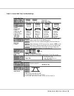
Process alarms use absolute high and low values to trigger an alarm. Use this alarm type if your
process may be subject to temperatures that it must not exceed. Use
[`AhI]
and
[`ALO]
to set
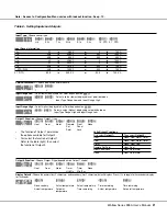
alarm points at or near these values. See Table 10:
[ALtY]
, next page.
•
Deviation alarms are triggered by a deviation from the set point. The alarm high value
[`AhI]
is
the deviation above set point, and the low value
[`ALO]
is the deviation below set point. Whenever
the set point is adjusted, the alarm settings are relative to that value. Deviation alarms use the cur-
rently controlling set point, whether primary, remote, idle, or 90% of primary, during auto-tuning. See
Table 10:
[ALtY]
, next page.
•
Normally Open,
[dEno]
or
[Prno]
, Alarms energize the alarm output when an alarm condition
occurs, and de-energize it when cleared. Use this type to activate external devices such as audible
alarms or lights. See Table 10:
[ALtY]
, next page.
•
Normally Closed,
[dEnc]
or
[Prnc]
, Alarms de-energize the alarm output when an alarm condi-
tion occurs, and energize it when the alarm is cleared. Use this type as a “deadman” switch where
system continuity is required for operation. See Table 10:
[ALtY]
, next page.
For example, by running the control output through the alarm output, you can set a normally
closed process alarm to disable the process when the process exceeds the alarm set point.
The alarm output will be off when power is off.
•
Alarm Hysteresis sets a point the process must pass on a return (from an alarm condition excur-
sion) to the
[`ALO]
and
[`AhI]
points before the alarm can clear. This prevents the alarm output
from “chattering” if the process is hovering around the alarm set point. See Table 10:
[AhYS]
, next
page.
•
Latching Alarms require the operator to clear them with a ß press after the process returns to a
safe, or non-alarm condition. Non-latching alarms self-clear. See Table 11:
[`LAt]
•
Silenced Alarms provide a means to clear the alarm output with a
ß
press even if the alarm
condition still exists. The flashing
[``hI
] or
[``LO]
message will persist until the alarm condition
ceases. See Table 11:
[`SIL]
[`SIL]
=
[`YES]
, alarms are disabled (no message or
output) on startup until the safe area is reached.
•
Alarm High and Low Points,
[`AhI]
and
[`ALO]
, in the Operations menu determine where
alarms will trigger. Alarm hysteresis
[AhYS]
determines where an alarm condition clears. See Table
•
To Clear an Alarm that is latched or “silence-able’ requires the operator to press the
ß
key after
the process returns to a safe, or non-alarm condition. Non-latching alarms self-clear. See Table 11:
[`LAt]
and
[`SIL]
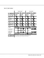
Table 10 (p. 25) and Table 11 (p. 27) illustrate the Series 935A alarm features.

