4 2
Watlow Series 935A User’s Manual
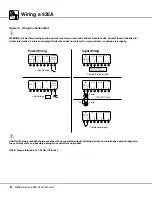
Wiring a 935A
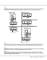
Figure 15 - Wiring the Series 935A
∫
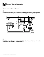
WARNING: All electrical wiring and fusing must conform to local and national electric codes. Contact local authorities for
further information. Failure to comply with electric codes could result in injury or death, or damage to property.
ç
CAUTION: Using grounded thermocouples with non-isolated output switching devices could introduce ground loops into
the control system, and possibly damage the controller and product.
NOTE: Torque terminals to 1.36 Nm (12 in lbs).
Low Voltage
S2
–
1
S1
+
2
–
3
+
4
5
6
7
8
OT1
IN
OT2
POWER
24-28
VOLTS
+ -
High Voltage
S2
–
1
S1
+
2
–
3
+
4
5
6
7
8
OT1
IN
OT2
POWER
100-240
VOLTS
Remote Set Point Input
S2
–
1
S1
+
2
–
3
+
4
5
6
7
8
OT1
IN
OT2
POWER
S2
–
1
S1
+
2
–
3
+
4
5
6
7
8
OT1
IN
OT2
POWER
2-wire
3-wire
S3
Thermocouple Input
S2
–
1
S1
+
2
–
3
+
4
5
6
7
8
OT1
IN
OT2
POWER
Power Wiring
Input Wiring


