background image

Watlow D4T Data Logger 

  208  

• 

Chapter 6 Appendix

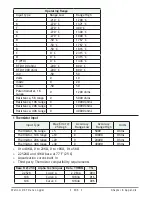
3 Universal Process/Retransmit Outputs

•  Universal process/retransmit, Output range selectable: 

- 0 to 10V 

Î

(dc) into a min. 4,000Ω load 

- 0 to 20mA into max. 800Ω load

Resolution

- dc ranges: 2.5mV nominal resolution
- mA ranges: 5 µA nominal resolution

Calibration Accuracy

- dc ranges: ±15 mV
- mA ranges: ±30 µA

Temperature Stability

- 100 ppm/°C

3 Mechanical Relay Outputs

•  2 Form C relays, 1 Form A relay. Form A shares common with 1 Form C relay
•  Each relay is rated at 5A, 24 to 240V

Å

 (ac) or 30V

Î


(dc)max., resistive load, 100,000 

cycles at rated load. Requires a min. load of 20mA at 24V, 125 VA pilot duty

4 Mechanical Relay Outputs

•  Form A, 5A each, 24 to 240V

Å

 (ac) or 30V

Î


(dc)max., resistive load, 100,000 cycles 

at rated load. Requires a min. load of 20mA at 24V, 125 VA pilot duty

2 Solid-State Relays

•  Form A, 10A max. each SSRs combined at 24V

Å

 (ac) min., 264V

Å

 (ac) max., opto-

isolated, without contact suppression, max. resistive load 10A per output at 240V

Å


(ac), max. 20A per card at 122°F (50°C), max.

•  12A per card at 149°F (65°C)

4 Solid-State Relays

•  Two pairs of SSRs, each pair shares a common
•  Form A, 24V

Å

 (ac) min., 264V

Å

 (ac) max., opto-isolated, without contact suppres-

sion, resistive load 2A per output at 240V

Å

 (ac), max. See table for max. current 

per output

Ambient Temperature

1 Module per Base

2 or More Modules

20°C

2.00A

1.50A

50°C

1.30A

1.00A

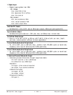
6 Digital Input/Output Option - (6 DIO)

•  Digital 

input update rate 10Hz

-  DC voltage


- Max. input 36V @ 3mA


- Min. high state 3V at 0.25mA


- Max. low state 2V

- Dry contact


- Min. open resistance 10KΩ


- Max. closed resistance 50Ω


- Max. short circuit 13mA

Summary of Contents for D4T

Page 1: ... Guide Registered Company Winona Minnesota USA ISO 9001 TOTAL 3Y earWarranty CUSTOMER SATISFACTION D4T Data Logger Setup and Operations 1241 Bundy Boulevard Winona Minnesota USA 55987 Phone 1 507 454 5300 Fax 1 507 452 4507 http www watlow com F4T cfm ...

Page 2: ...nit can provide Consult QSG for further infor mation AVERTISSEMENT mise en garde ou danger qui demande plus de précisions que l information sur l étiquette de l unité Consultez le manuel de l utilisateur pour plus d informations Unit can be powered with either alternating current ac voltage or direct current dc voltage ESD Sensitive product use proper grounding and handling tech niques when instal...

Page 3: ...re Systems Limited All rights reserved 2008 2014 Crank Software Inc All rights reserved Watlow and Composer are registered trademarks of Watlow Electric Manufacturing Company UL is a registered trademark of Underwriter s Laboratories Incorporated Modbus is a registered trademark of Schneider Automation Incorporated Vaisala is a registered trademark of Vaisala OY Corporation Microsoft and Windows a...

Page 4: ...Composer 26 Setting Up Data Log Files Using Composer 26 Chapter 3 Using the D4T Front Panel 35 Navigating and Understanding the User Interface UI 35 Understanding D4T Menus 35 Multiple Languages 35 Event Driven Menus 36 Home Screen Described 37 Front Panel Navigational Buttons 38 Configuring Ethernet Communications 39 Default Ethernet Parameters and Settings 39 Personalizing the Home Screen Using ...

Page 5: ...2 Logic 89 Math 97 Signals 98 Process Value 111 Special Output 123 Thermistor Input 126 Timer 129 Universal Input 136 Variable 147 Chapter 6 Appendix 150 Communications 150 Introduction to Standard Commands for Programmable Instruments SCPI 150 Introduction to the Modbus Protocol 150 Modbus Table Orientation 151 D4T Base Specifications 198 Flex Modules and Limit I O Specifications 202 Flex Modules...

Page 6: ...Your Comments are Appreciated In an effort to continually improve our technical literature and ensuring that we are providing information that is useful to you we would very much appreciate your comments and sugges tions Please send any comments you may have to the following e mail address TechlitComments watlow com Technical Assistance If you encounter a problem with your Watlow data logger revie...

Page 7: ...the RMA number is on the outside of the carton and on all paperwork returned Ship on a Freight Prepaid basis 3 After we receive your return we will examine it to verify the reason for the product failure Unless otherwise agreed to in writing Watlow s standard warranty provisions which can be located at www watlow com terms will apply to any failed product 4 In the event that the product is not sub...

Page 8: ...g for several different alarm situations and then driving output devices such as heaters audible alarms and lights Each process needs to be thought out carefully and the data logger s inputs functions and outputs set up properly As an example the graphic below illustrates the Function Block Diagram as seen when using Composer software The application requirements in this example are simple and def...

Page 9: ...f voltage or resistance and each system can be equipped with multiple digital I O modules Each I O point must be configured to func tion as either an input or output Functions Functions use input signals to calculate a value and or performs an action A function may be as simple as reading a digital input as on or off or reading an analog value temperature to set an alarm state to on or off As an e...

Page 10: ...L or M in the fifth character of its part number see D4T Ordering Information Logging can be enabled at any time and is intended to capture real time data for a user selectable list of data points With firmware revision 3 0 and above several new features are available 1 User can determine if logged files will be moved automatically and or manually 2 Destination of the saved file can be directed to...

Page 11: ...lls automatically if not already on target machine Installing the Software To install the software 1 Double click the Setup exe 2 Select the language of choice and click the OK to proceed 3 Click the Next button to proceed 4 After reading the Composer software license agreement click the I accept the terms in the License Agreement radio button and then click on the Next button to proceed 5 The nex...

Page 12: ...ile enc or csv Depending on files size this may take several minutes to open To decrypt an encrypted file follow the steps below 1 If data logging has not yet been stopped do so now by pushing Main Menu Data Log ging Stop buttons Note When data logging is stopped allow at a minimum six minutes for closure of all files and movement of those files to the selected destination before attempting de cry...

Page 13: ...file to your liking Note The largest file size allowed is 1GB If decrypting a file of this size it could take up to 10 minutes to complete Connect to a System Opens a window showing all available communications ports Online Systems Displays all connected systems Open a System Image Opens a dialog box showing the default folder structure To import a system image follow the steps below 1 Connect to ...

Page 14: ...ttings set temperature units and AC line frequency for the system Security allows for multiple levels of password protection Saving a System Image save a system image to a storage device Import System Image restore a system image from a storage device to the data logger The graphic below shows the first displayed screen System Overview after connecting to a system Connecting to an Online System To...

Page 15: ...allows the administrator to determine and set security privileges to avoid un wanted changes Device Menus When clicked a drop down submenu will appear allowing navigation to device level menus Each device will have one of three flags displayed immediately to its left Those flags are described in the following table Symbol Menu Item Description Pluggable Modules All expected modules and no unexpect...

Page 16: ...th Password requires a password admin sets feature access is permitted to change the password for this user group Maintenance User requires a password admin sets feature access is permitted to change the password for this user group Admin requires a password has unlimited access to features sets permissions and pass words for all user groups The Admin user can set permissions for each user group t...

Page 17: ...ry to contact the OEM or as a last resort Watlow Technical Assistance Note Once security is applied to the data logger only the administrator Admin can reconfigure or remove the security Note When the system file is saved any applied security will be saved with it Save Image After clicking on save image as the save button will become active gray to white This al lows a user to make changes to the ...

Page 18: ...select the destination folder for the image 4 Enter the desired filename 5 Click Save Note The system image filename will always have the extension wsi for Watlow System Image and cannot be changed Note The real time clock values are not saved or imported Import Image Restore a system image from a storage device to the data logger The list below shows what is restored Device Details Pluggable Modu...

Page 19: ...ght should be applied prior to importing Device Details The Device Details allows a user to make changes to the system settings described below De scriptions are numbered correspondingly in the graphic that follows Navigate to Device Details 1 From any screen click on the Device menu tab to drop down a submenu 2 Click the Device Details button Device Name change the name 32 characters maximum of t...

Page 20: ...tics Symbols Related to Pluggable Modules description of the symbols that may be displayed when using Composer software Configuring Flex Modules configuration process described Entering FM Information Before Module Installation detailed description of the why and how a user would do this prior to acquiring the module Note The graphic below represents a data logger that first had its flex modules i...

Page 21: ... bar the symbol that will be displayed to the left of the Pluggable Modules button will be of the most significance The red exclamation will al ways take precedence Symbol Description The expected module has been detected No module has been detected in a slot the data logger expects to be emp ty A module has been detected in a slot the data logger expects to be empty The data logger expects a modu...

Page 22: ...acquired simply plug it into its assigned slot and click the Detect Mod ules button After doing so the data logger will restart and a green flag will be displayed for that slot number Configuring the Application using the Function Block Diagram The Function Block Diagram FBD view is used to connect the real world inputs and outputs to internal data logger functions To enter the Function Block Diag...

Page 23: ...able floating screens Function Block Diagram View Screen Orientation The FBD View has the following features numbered correspondingly in the graphic below Function Block Diagram All FBs are placed and con nected on the canvas Function Block Library Shows the available FBs for this data logger The number below each icon indicates how many FBs of that type remain available for use with this data log...

Page 24: ...am Environment The Parameter Help Library and Navigator windows can be moved from their default loca tions to allow a user to maximize the visibility of the FBD diagram See the procedures below regarding how to float hide and dock these win dows Window Anchor Points While dragging a window or a grouping of windows to a new docking location Anchor Points will appear on the screen The anchor points ...

Page 25: ...ger for specific applications The signals that carry data between function blocks normally appear as black lines in the dia gram but when the block that transmits the signal cannot determine what the correct value should be the signal changes to yellow indicating the error Each FB s response to errors re ceived is explained in the description of the function block Warning Once an output FB receive...

Page 26: ... or receivers Clicking a trans mitter or receiver begins to draw a signal rather than move the FB The canvas will scroll if the mouse pointer is close to the edge but not outside the dia gram window To make a long move click the block to select it then zoom out to make it easier to move the block to the desired location Connecting Function Blocks Together To connect a transmitter to a receiver Cli...

Page 27: ... signal which will display the error 3 In this particular example the error is identified as an Open sensor 4 Click on the selected FB and view the Help window 5 Search Ctrl F the help file for the word Open 6 Once found evaluate make note or correct the cause of the problem If further assistance is needed review the associated product User s Guides or contact the Watlow Technical Support team 1 8...

Page 28: ...of windows Click the pin auto hide icon in the window s title bar To use a window that is hidden Mouse over point the mouse cursor at the window name Floating Windows To float a window or a group of windows Click and drag the window s title bar to the desired location To separate a window from a group Click and drag the window name to the desired location Docking Windows To return a floating windo...

Page 29: ...ed menu to be viewed on the UI r Change the user interface screen brightness To personalize the home screen From the device menu choose Personalization from the drop down menu Much if not all of what is displayed on the home pages comes from the FBD Therefore it would make sense to first configure the FBD prior to personalizing the home screen The personalization settings shown above would produce...

Page 30: ...s lost while the data log file itself will be main tained where it was captured Setup Data Logging To setup data logging follow the steps below 1 Click on the Device Menu tab 2 From the drop down menu click on Data Logging 3 Select and add all of the desired Data Points for the data log file Note Selected data points will be used whenever data logging is enabled 4 Click on the Setup button Logging...

Page 31: ...rwrite or Stop Note Logging to USB allows for Stop only when memory is full Date Format MM DD YYYY or DD MM YYYY Note Applies to each individual log entry alone does not apply to filename Time Format 12 or 24 hour clock Note Applies to each individual log entry alone does not apply to filename 5 Click on the File Transfer button Auto Transfer Type None TFTP Samba or USB Note When automatic file tr...

Page 32: ...ata log files in in ternal memory Data logging has not yet been started Files have already been moved from internal memory Transfer Complete All data log files have been moved from inter nal memory File transfer initiated and completed successfully Transferring Files Data log files being moved from internal memory File transfer initiated and in progress Server Down Connectivity from client to serv...

Page 33: ...ed Configuring a Samba Shared Folder below Configuring a Samba Shared Folder Samba also known as Server Message Block SMB Common Internet File System CIFS is fully supported by Windows File Sharing Within this document SMB CIFS will be referred to as Samba Samba when in use creates a directory on the D4T device that maps to a shared directory on the user s PC There are several ways that a Windows ...

Page 34: ...lorer and create a new folder Note The name of the shared folder must not contain any slashes or back slashes Note If the folder being created is a sub folder off of the root directory right click on the created folder select Properties Sharing Ad vanced Sharing and check Share this folder Doing this will allow the sub folder path to be defined as if it were in the root directory of the selected d...

Page 35: ...re the File Transfer function within the data logger The graphics below show all fields that must be filled in to do an automatic transfer of the data logged file to the shared folder identified in this example as SambaStore Note Transferring files via Samba may be accomplished by 2 methods Auto transfer and a user initiated transfer Once the automatic transfer is enabled this function will move t...

Page 36: ...MB in size will be moved from internal memory to the shared folder SambaStore Configuring a Trivial File Transfer Protocol TFTP Server In order to use the TFTP file transfer option a TFTP server must be setup and running on your computer to service the TFTP transfers from the D4T The user will need to specify the IP address of the remote computer and also the remote computer name TFTP requires no ...

Page 37: ...p Data Logging and follow the procedure to de fine what it is to be captured within the file Within this same procedure step 5 it will be important to define the IP address of the remote computer while also determining whether the file will be transferred manually or automatically 3 Start the TFTP server and then start data logging by pushing the following buttons on the D4T front panel Main Menu ...

Page 38: ...t Options Actions Control PID Loops Profile Events Inputs Outputs Alarms Limits Machine Con trols My Menu Sel ect Parameters Control PID Loops Profile Settings Inputs Outputs Alarms Limits Machine Con trols Keys Network Global Update Display Start Annotation Logged Data Points Select Data Points Setup Data Log File Transfer Actions User Selected Parameters Import Export Samba TFTP Location de pend...

Page 39: ...ional display as shown below Event Driven Menus During normal operation it is possible that an event can occur that will present the user with indications pop up windows and menu selections that are not shown above As an example if an alarm occurs the status bar top of screen shot shown below will indicate its existence by blinking yellow If the user pushes the status bar down button to view the a...

Page 40: ...cess to other opera tional parameters such as the Closed Loop Set Point Autotune PID settings etc see Control Mode Navigation Keys and Displays After initially powering up the data logger a white initialization screen will appear first Once the startup process is complete the splash screen shown below will appear As described in the splash screen above After first time power up do the following 1 ...

Page 41: ...ws on each side of the home screen provides navigation from one to the other 4 Output Widget Bar user configurable events function keys or output status on off This can be relocated on the screen see Personalizing the Home Screen Front Panel Navigational Buttons When looking at the front panel of the D4T at the bottom of the display four push buttons are displayed as icons shown below The text in ...

Page 42: ...roller registers 1 D4T 2 F4 compatibility Configuring Ethernet Communications To change Ethernet parameters 1 Push the Menu Settings and Network buttons in that order 2 Push Ethernet 3 Change desired settings For Ethernet connectivity options and step by step instructions on connecting the D4T into an Ethernet network see chapter 3 of the D4T Installation and Troubleshooting User s Guide Default E...

Page 43: ...ure pluggable modules and at least one control loop To personalize the Home screen do the following 1 From any screen push the Menu button 2 Push Personalize 3 Push Basic Personalization 4 Select the desired Home Layout by pushing Main Top Main Center or Main Bottom The red arrows were placed on this graphic for emphasis only and represent what the focus of this operation is that being defining th...

Page 44: ...for the right 8 Push the Home screen button to see the result of this operation Redefining page 1 to display two loops content blocks 1 From any screen push the Menu button 2 Push Personalize 3 Push Basic Personalization 4 Select the desired Home Layout by pushing Main Top Main Center or Main Bottom 5 Push Page 1 6 Select two content blocks ...

Page 45: ...meters Pushing the vertical ellipsis or anywhere within the red box shown below will provide access to the data logger name and many other parameters Some of the available options accessible through this access point are shown below Be aware that what is visible and accessible here varies based on user settings F4T with USB Mouse Feature ...

Page 46: ...p 1 Set up Load Batch and Unload Batch fields the end user will be prompted to scan for the job Daily Operations 2 Batch Entry Load Operator will scan in bar code fields being requested by controller 3 Batch Entry Unload Operator will scan in bar code fields being requested by controller 1 Create Load Batch bar code fields the operator will be asked to scan 2 3 Edit name 4 5 6 7 Edit field or list...

Page 47: ...ch and Unload Batch fields the end user will be prompted to scan for the job Daily Operations 2 Batch Entry Load Operator will scan in bar code fields being requested by controller 3 Batch Entry Unload Operator will scan in bar code fields being requested by controller User bar code scanner to enter desired part s All parts scanned in Finish scanning in all bar code fields Data log recording ...

Page 48: ...Load Batch and Unload Batch fields the end user will be prompted to scan for the job Daily Operations 2 Batch Entry Load Operator will scan in bar code fields being requested by controller 3 Batch Entry Unload Operator will scan in bar code fields being requested by controller User Kirk scanned in their ID as the unloading operator Batch report is automatically generated by controller ...

Page 49: ...ch Bar code data Thermal Data Transfer file on USB stick into a PC to view file Microsoft Excel view of Batch Report CSV file format Creating and viewing encrypted data files are also available Details covered in Watow F4T videos available on line Want to learn more Data logging video https www youtube com watch v QC dnzoKEXQ t 0s index 2 list PLa QlQSMB2FG3K7m mnhLubeh9W6bJcBZJ Data log batch rep...

Page 50: ...blue box above View All Outputs displays all connected outputs by their name if given Change View defines widget location Cancel Returns to the Home screen 2 Push the Change View button 3 Push the desired position 1 to 4 and define its function 4 Push the Done button when complete Data Logging Data Logging can be enabled at any time and will log a user selectable list of data points While data log...

Page 51: ...Memory Log Interval defines the frequency in which the log will be written 0 1 second to 60 minutes File Type Encrypted enc Comma Separated Values csv or Both File Size Limit 20MB when using TFTP or Samba 1GB when using USB Memory Full Action when log to device defined above is full Overwrite or Stop Note Logging to USB allows for Stop only when memory is full Date Format MM DD YYYY or DD MM YYYY ...

Page 52: ...TP or Samba is selected above the server must be configured For instructions on how to configure either or both click on the server of choice TFTP or Samba Flashing the Data Logger Firmware On occasion the D4T firmware may be updated When flashing the firmware ensure that pow er to the data logger is not disrupted and allow the process to proceed to completion Once the process is complete the data...

Page 53: ...eflect the same state it was in when the flashing activity was started For example if the data logger was in auto mode it will be returned to auto mode Note After the data logger has been updated the USB Flash Drive needs to be removed from the data logger If it remains when the data logger power is cycled the firmware flash will occur again Step 1 of 3 Moving file froom USB flash drive to F4T Ple...

Page 54: ...rm In this example Universal Input 1 on module 1 measures the temperature of a chamber or oven with a thermocouple Alarm 1 monitors the temperature from the universal input which is also used by the control loop as feedback for heat control When the temperature goes outside the normal range defined by the user adjustable alarm set points output 1 on module 4 a form C relay energizes an audible ala...

Page 55: ...block can receive the analog input signal Make sure the input block s Sensor Type and other parameters are set correctly for your sensor By default the alarm s type setting is Off Set it to Process Alarm Set the alarm s Sides setting to High or Low if you want to monitor only for the pro cess value going too high or too low or set Sides to Both if you want the alarm to occur when the process value...

Page 56: ...xternal devices as is shown in this example Enter names for blocks where possible to make the application easier to understand A deviation alarm uses the signal received at CTR as the center of the deviation band The high and low alarm set points are relative to that center value In most devia tion alarm applications users want the alarm deviation centered on a control loop s set point as shown in...

Page 57: ...plication Tips Process blocks are initially located in the library and can be dragged to the canvas You can connect up to four sensors to the Process block The process block passes along the signal from the lowest number receiver that has no error on its sensor signal The signal transmitted by the process block can be used by a control loop or any other function as if it was received directly from...

Page 58: ... Than 69 Equal To 69 Not Equal To 70 Greater or Equal 71 Less or Equal 71 Counter 72 UP 72 Down 74 Digital Inputs Outputs I O 75 Input Dry Contact 75 Output 76 Input Voltage 77 Digital Outputs 78 Solid State Relay Switched DC Open Collector 78 Electromechanical Relays 80 Key 81 Momentary 81 Toggle 81 On Pulse 82 Linearization 82 Off 82 Interpolated 83 Stepped 85 Logic 89 Off 89 And 89 Nand 90 Equa...

Page 59: ... Multiply 105 Absolute Difference 105 Minimum 106 Maximum 107 Square Root 107 Sample and Hold 108 Pressure to Altitude 108 Dew Point 109 Process Value 111 Off 112 Sensor Backup 112 Average 113 Crossover 113 Wet Bulb Dry Bulb 114 Switch Over 115 Differential 116 Ratio 116 Add 117 Multiply 117 Absolute Difference 118 Minimum 118 Maximum 119 Square Root 119 Vaisala RH Compensation 120 Pressure to Alt...

Page 60: ...cial Output 123 Off 123 Compressor Control 123 Thermistor Input 126 Timer 129 Off 129 On Pulse 130 Delay 131 One Shot 132 Retentive 134 Universal Input 136 Millivolts Volts 137 Off 139 Thermocouple 140 Milliamps 141 Resistance Temperature Device RTD 100 and 1000 Ohm 143 1K Potentiometer 144 Variable 147 Analog 147 Digital 149 ...

Page 61: ...nd a parameter is provided for choosing which state triggers the action 2 Units An analog signal can be in units of absolute or relative temperature Celsius or Fahr enheit percent power or relative humidity Values may have no units or unspecified units indicated as process Digital signals have no units associated with them Units Description Absolute Temperature The value is a temperature on the Ce...

Page 62: ... failure has occurred Not Sourced The source FB is missing a required signal at one of its receiv ers Stale Data Data sourced from another data logger has become unavailable Math Error A calculation has no defined result such as divide by zero This chapter describes in detail each of the available functions as well as their associated pa rameters Note The addresses and other information required t...

Page 63: ...mitter Digital Indicates the alarm state see Logic Name Uniquely identify this FB using up to 20 alphanumeric characters Type To monitor an analog signal for alarm conditions set Type to Process Alarm Sides Select whether the receiver IN is monitored for high low or both high and low alarms Options Both IN is monitored for high low or both high and low alarms High IN is monitored for a high alarm ...

Page 64: ... an acceptable level Options Latching alarm remains active until the condition that caused it no longer exists and the alarm is reset by the CLR receiver or the Clear Alarm parameter Non latching alarm clears automatically once the condition that caused it no longer exists Blocking Alarm blocking allows a system to warm up after being powered up or to be adjusted without experiencing nuisance alar...

Page 65: ...d to minimize nuisance alarms Range 0 to 9 999 seconds Low Set Point Set the process value or temperature that triggers the low process alarm Range 99 999 to 99 999 High Set Point Set the process value or temperature that triggers the high process alarm Range 99 999 to 99 999 Clear Alarm Set this parameter to clear to reset the alarm state after correcting the condition that caused the alarm Optio...

Page 66: ...alog signal for alarm conditions relative to another signal set Type to Devia tion Alarm Sides Select whether the receiver IN is monitored for high low or both high and low alarms Options Both IN is monitored for high low or both high and low alarms High IN is monitored for a high alarm only The low alarm is not monitored Low IN is monitored for a low alarm only The high alarm is not monitored Hys...

Page 67: ...ns active until the condition that caused it no longer exists and the alarm is reset by the CLR receiver or the Clear Alarm parameter Non latching alarm clears automatically once the condition that caused it no longer exists Blocking Alarm blocking allows a system to warm up after being powered up or to be adjusted without experiencing nuisance alarms Set alarm blocking to prevent alarms before IN...

Page 68: ...rm The low deviation alarm occurs when the value at IN is below the center s value CTR plus this param eter s setting A negative value for Low Set Point sets the alarm condition below the center and a positive value sets the alarm condition above the center Range 99 999 to 99 999 High Set Point Set how far the value at IN must rise above CTR to trigger a high deviation alarm The high deviation ala...

Page 69: ...DC output the value received is scaled proportionally from the 0 to 100 input range to the 4 to 20 output scale When the input is 25 the output is 8 mADC For a retransmit output to a 0 to 10 VDC output the value received at input In is scaled pro portionally from the 50 to 250 input range to the 0 to 10 output scale When the input is 100 the output is 2 5 VDC Note that the settings of the Range Lo...

Page 70: ... Scale High Set the desired value for the output in electrical units mA DC or VDC when the input to the block equals the Range High setting Scale High and Range High are the coordinates of a point on the line that relates the input to the scaled output Consult the hardware specifications for the signal range supported by the specific hardware Range 100 0 to 100 0 mA DC typically 20 mA DC 100 0 to ...

Page 71: ...ut is on when input A is less than input B Equal To the block s output is on when the two inputs are equal Not Equal To the block s output is on when the two inputs are not equal to each other Greater or Equal the block s output is on when input A is greater than or equal input B Less or Equal the block s output is on when input A is less than or equal to input B Off When the Compare block s funct...

Page 72: ... exists on any receiver the function cannot definitively determine the result of the comparison and an error will be generated Use Error Handling to select the output s val ue and error status Options True Good outputs value is true on with no error True Bad outputs value is true on and has an error False Good outputs value is false off with no error False Bad outputs value is false off and has an...

Page 73: ...al to each other See Tolerance Signals Direction Label Type Function Receiver A Analog Signal to be compared to B B Analog Signal to be compared to A Transmitter T F Digital On when A and B are not equal and within tolerance other wise off Function To test if A and B are not equal to each other set Function to Not Equal To Tolerance Use Tolerance to set how precisely A and B must match to be consi...

Page 74: ...t Range 0 to 99 999 Error Handling When an error exists on any receiver the function cannot definitively determine the result of the comparison and an error will be generated Use Error Handling to select the output s val ue and error status Options True Good outputs value is true on with no error True Bad outputs value is true on and has an error False Good outputs value is false off with no error...

Page 75: ...tal signal s state changes a given number of times A counter can count up or down from the load value Its output turns on when the count equals the target value The output turns off and the count is set equal to the load value when the reset signal is received This block is found in the Function Block Diagram editor s Library when working with a data logger that offers the Counter block The number...

Page 76: ...t equals the target value Additional counts cause the output to turn off Count Active Level Set which state changes at CNT are counted Options Both the count increments when CNT changes from on to off and when it changes from off to on High the count increments only when CNT changes from off to on Low the count increments only when CNT changes from on to off Reset Active Level Set which state chan...

Page 77: ... which the Count parameter is set each time the data logger is powered up and whenever the counter is reset by RST Range 0 to 9 999 Latching Select the behavior for the output when Count exceeds the Target Value Options Yes output is latched on once the count reaches the target value and turns off only when the counter is reset No the output is on only when the count equals the target value Additi...

Page 78: ...ts I O Use a digital input output block to connect a field I O device s signal to the application This FB can be configured as either a digital input that can be triggered by an external device or a digital output that can switch an external device As an output the block can accept either a digital on off signal or an analog percentage signal The block is configured as an input or output with the ...

Page 79: ...100 the output is on Name Uniquely identify this FB using up to 20 alphanumeric characters Direction To configure the I O point to drive the physical output set Direction to Output Time Base Type Choose the method used to operate the output when the input is an analog percentage With either of the methods the output switches off and on such that the average amount of time the output is on equals t...

Page 80: ...e value set with High Power Scale Values between 0 and 100 are scaled proportionally See the il lustration to the right Range 0 0 to 100 0 High Power Scale Set the maximum power level for the output When the input equals 100 on the output is equal to the value set here When the input equals 0 off the output is equal to the value set with Output Low Power Scale Values between 0 and 100 are scaled p...

Page 81: ...tly Solid State Relay Switched DC Open Collector These blocks are found on the canvas in the Function Block Diagram editor The number of these blocks available depends on the number of solid state relays switched DC outputs and open collector outputs on the flex modules installed in the data logger Signals Direction Label Type Function Receiver Analog or Digital Off or 0 the output is off Between ...

Page 82: ...ree and when 50 power is called for the output is on for three ac cycles and off for three This method is appropriate for solid state relays but not for electromechani cal relays mercury displacement relays inductive loads or heaters with unusual resis tance characteristics Fixed Time Base Set the duration of one on off cycle This applies when the Time Base Type is set to Fixed Time Base Range 0 1...

Page 83: ...ver Analog or Digital Off or 0 the output is off Between 0 and 100 the output switches according to the Fixed Time Base setting On or 100 the output is on Name Uniquely identify this FB using up to 20 alphanumeric characters Fixed Time Base Set the duration of one on off cycle A percent output power is converted to a duty cycle over the Fixed Time Base For example if the Fixed Time Base is ten sec...

Page 84: ...oft key is being pressed Toggle the transmitted signal changes state each time the soft key is pressed On Pulse the block transmits an on signal of a specified duration when it is pressed This function is found in the Function Block Diagram editor s Library The number of these blocks available to be added to the diagram is shown within the paren thesis Momentary The transmitted signal is on while ...

Page 85: ...ding to a 10 point scaling curve and an offset This block is found in the Function Block Diagram editor s Library when working with a data logger that offers the Linearize block Within the Library the number of these blocks available is shown in parenthesis Choose the type of scaling curve with the Function parameter These options for the Function parameter are described in detail in the following...

Page 86: ...terpolate Units Set the units of the output value Options Source the output has the same units as the signal connected to the top receiver None the output is a pure number without units Absolute Temperature the output is a temperature on the Celsius or Fahrenheit scale For example 33 F as an absolute temperature is one degree above the freezing point of water An absolute temperature can be used as...

Page 87: ...curve This value is scaled to Output Point 3 Range 99 999 000 to 99 999 000 Output Point 3 Set the value to which the input is scaled when the input is equal to Input Point 3 Range 99 999 000 to 99 999 000 Input Point 4 Set the forth lowest input value on the scaling curve This value is scaled to Output Point 4 Range 99 999 000 to 99 999 000 Output Point 4 Set the value to which the input is scale...

Page 88: ...put value on the scaling curve This value is scaled to Output Point 9 Range 99 999 000 to 99 999 000 Output Point 9 Set the value to which the input is scaled when the input is equal to Input Point 9 Range 99 999 000 to 99 999 000 Input Point 10 Set the tenth lowest input value on the scaling curve This value is scaled to Output Point 10 Range 99 999 000 to 99 999 000 Output Point 10 Set the value...

Page 89: ...res 120 C and 100 C is 20 degrees but it is not the temperature 20 C A relative tem perature is appropriate for use as a calibration offset or a deviation alarm set point Power the output is a percentage with 100 representing full power and 0 represent ing no power Process the output is in units of measure other than degrees Fahrenheit degrees Cel sius or relative humidity Relative Humidity the ou...

Page 90: ... Range 99 999 000 to 99 999 000 Input Point 5 Set the fifth lowest input value to be scaled Input values equal to or greater than this but less than Input Point 6 are scaled to Output Point 5 Range 99 999 000 to 99 999 000 Output Point 5 Set the value to which the input is scaled when the input is greater than or equal to Input Point 5 and less than Input Point 6 Range 99 999 000 to 99 999 000 Inp...

Page 91: ... or greater than this but less than Input Point 10 are scaled to Output Point 9 Range 99 999 000 to 99 999 000 Output Point 9 Set the value to which the input is scaled when the input is greater than or equal to Input Point 9 and less than Input Point 10 Range 99 999 000 to 99 999 000 Input Point 10 Set the tenth lowest input value to be scaled Input values equal to or greater than this are scaled...

Page 92: ...inputs are false or all the inputs are true the output is true Otherwise the output is false Not Equal To if all the inputs are false or all the inputs are true the output is false Other wise the output is true Or if any input is true the output is true If all inputs are false the output is false Nor if any input is true the output is false If all inputs are false the output is true Latch when the...

Page 93: ...Error Handling to select the output s value and error status when the function cannot de finitively determine the result Options True Good output s value is true on with no error True Bad output s value is true on and has an error False Good output s value is false off with no error False Bad output s value is false off and has an error Nand If any input is false off 0 the output is true on 100 If...

Page 94: ...or Handling to select the output s value and error status when the function cannot de finitively determine the result Options True Good output s value is true on with no error True Bad output s value is true on and has an error False Good output s value is false off with no error False Bad output s value is false off and has an error Equal To If all the inputs are false off 0 or all the inputs are...

Page 95: ...se Error Handling to select the output s value and error status when the function cannot de finitively determine the result Options True Good output s value is true on with no error True Bad output s value is true on and has an error False Good output s value is false off with no error False Bad output s value is false off and has an error Not Equal To If all the inputs are false off 0 or all the ...

Page 96: ...l To Error Handling Use Error Handling to select the output s value and error status when the function cannot de finitively determine the result Options True Good output s value is true on with no error True Bad output s value is true on and has an error False Good output s value is false off with no error False Bad output s value is false off and has an error Or If any input is true on 100 the ou...

Page 97: ...ling Use Error Handling to select the output s value and error status when the function cannot de finitively determine the result Options True Good output s value is true on with no error True Bad output s value is true on and has an error False Good output s value is false off with no error False Bad output s value is false off and has an error Nor If any input is true on 100 the output is false ...

Page 98: ...vely determine the result Options True Good output s value is true on with no error True Bad output s value is true on and has an error False Good output s value is false off with no error False Bad output s value is false off and has an error Latch When the HOLD input is false off 0 the output follows the IN input value When HOLD is true on 100 the output does not change it is held latched at the...

Page 99: ...rror True Bad output s value is true on and has an error False Good output s value is false off with no error False Bad output s value is false off and has an error RS Flip Flop True on 100 at the Set input sets the output to true on 100 unless the reset Rst input is true on 100 Whenever Rst is true on 100 the output is false off 0 To understand the RS Flip Flop s behavior consider these scenarios...

Page 100: ... Hold has an error The output s value and error follow the input RS Flip Flop SET input gets an error while the output is false The output stays false with no error SET input gets an error while the output is true The output stays true with no error until the RST input resets the output to false RST input gets an error while the output is false The output stays false with no error until the SET in...

Page 101: ...tputs the greatest of up to four inputs Square Root calculates square root of an input Sample and Hold freezes an analog signal with a digital input Pressure to Altitude calculates the standard distance above sea level based on an atmospher ic pressure Dew Point calculates the temperature at which water vapor will condense based on the tem perature and relative humidity of an environment Off The o...

Page 102: ... result of the calculation Range 99 999 000 to 99 999 Filter Set the amount of filtering to apply Filtering smooths signal fluctuations Increase the time to increase filtering Excessive filtering slows the function s response Range 0 0 to 60 0 seconds Switch Over When SW is off the output equals input 1 When SW is on the output equals input 2 A filter and offset may be applied to the output The ou...

Page 103: ...es are converted according to the line defined by the two points Scale High need not be greater than Scale Low and Range High need not be greater than Range Low A filter and offset may be applied to the calculated value Process Scale can be used for example to convert from one set of units to another or to con vert a sensor signal to engineering units if the signal is linear with the value it repr...

Page 104: ...ab solute temperature For example the difference between the two measured tempera tures 120 C and 100 C is 20 degrees but it is not the temperature 20 C A rela tive temperature is appropriate for use as a calibration offset or a deviation alarm set point Power the output value is a percentage signal where 100 represents full power and 0 represents no power Process the output is in units of measure...

Page 105: ...n is not limited to values be tween Range Low and Range High Input values are converted according to the line defined by the two points Scale High need not be greater than Scale Low and Range High need not be greater than Range Low A filter and offset may be applied to the calculated value The out put has the same units as input DEV Deviation Scale may be used instead of Process Scale when it is d...

Page 106: ...EV to calculate the output Range 99 999 000 to 99 999 000 Range High Set the adjustment to be added to input DEV when input X equals the Scale High setting Scale High and Range High are the coordinates of a point on the line that relates input X to the adjustment added to input DEV to calculate the output Range 99 999 000 to 99 999 000 Offset Adjustment added to the result of the calculation Range...

Page 107: ...red result of the calculation X Y plus the off set Function To divide one input by another set Function to Ratio Offset Adjustment added to the result of the calculation Range 99 999 000 to 99 999 000 Filter Set the amount of filtering to apply Filtering smooths signal fluctuations Increase the time to increase filtering Excessive filtering slows the function s response Range 0 0 to 60 0 seconds A...

Page 108: ...wise the output s units are those of the signal connected to the top input Signals Direction Label Type Function Receivers Analog Value to be multiplied Analog Value to be multiplied Analog Value to be multiplied Analog Value to be multiplied Transmitter Analog The filtered product of the inputs plus the offset Function To compute the product of up to four inputs set Function to Multiply Offset Ad...

Page 109: ... 0 seconds Minimum This function selects the minimum of up to four inputs Only inputs connected to a source are considered A filter and offset may be applied to the output The output has the units of the signal with the minimum value Signals Direction Label Type Function Receivers Analog Compared with other inputs Analog Compared with other inputs Analog Compared with other inputs Analog Compared ...

Page 110: ...99 999 000 Filter Set the amount of filtering to apply Filtering smooths signal fluctuations Increase the time to increase filtering Excessive filtering slows the function s response Range 0 0 to 60 0 seconds Square Root This function calculates the square root of input X A filter and offset may be applied to the calculated value The output has the same units as X Signals Direction Label Type Func...

Page 111: ...d Hold Offset Adjustment added to the result of the calculation Range 99 999 000 to 99 999 000 Filter Set the amount of filtering to apply Filtering smooths signal fluctuations Increase the time to increase filtering Excessive filtering slows the function s response Range 0 0 to 60 0 seconds Pressure to Altitude This function determines the altitude based on the atmospheric pressure A filter and o...

Page 112: ...emperature and relative humidity A filter and offset may be applied to the calculated value The output is an absolute temperature Signals Direction Label Type Function Receivers T Analog Temperature measurement RH Analog Relative humidity measurement Transmitter Analog Filtered calculated dew point plus the offset Function To calculate the temperature at which water vapor will condense based on th...

Page 113: ...e output is equal to the offset and has an error SW has an error The function considers the switch to be off Differen tial X or Y or both have errors The output is equal to the offset and has an error Ratio X or Y or both have errors The output is equal to the offset and has an error Y equals zero The output is equal to the offset and has an error Add Any or all inputs have errors The output is eq...

Page 114: ...The type of conditioning performed by the process block depends on the setting of the Function parameter These options for the Function parameter are described in detail in the following sections Off the output follows the filtered input plus the offset Sensor Backup automatically switches to the next of up to three alternate inputs when a sen sor fails Average calculates the average of up to four...

Page 115: ...nge 0 0 to 60 0 seconds Sensor Backup This function passes the first input that has no error as the output The inputs are considered as backups in numerical order If input 1 has no error the output follows input 1 If input 1 has an error and input 2 does not the output follows input 2 and so on Only inputs connected to a source are considered as backups A filter and offset may be applied to the ou...

Page 116: ...on to Average Offset Adjustment added to the result of the calculation Range 99 999 000 to 99 999 000 Filter Set the amount of filtering to apply Filtering smooths signal fluctuations Increase the time to increase filtering Excessive filtering slows the function s response Range 0 0 to 60 0 seconds Crossover The output of this function follows input A at the low end of the range and over a user de...

Page 117: ...Set the width of the transition between input A and B Range 99 999 000 to 99 999 000 seconds Offset Adjustment added to the output Range 99 999 000 to 99 999 000 Filter Set the amount of filtering to apply Filtering smooths signal fluctuations Increase the time to increase filtering Excessive filtering slows the function s response Range 0 0 to 60 0 seconds Wet Bulb Dry Bulb This function calculat...

Page 118: ... Over When SW is off the output equals input 1 When SW is on the output equals input 2 A filter and offset may be applied to the output The output has the same units as the selected in put Signals Direction Label Type Function Receivers DRY Analog Selected as the output when SW is off WET Analog Selected as the output when SW is on SW Digital Off selects input 1 on selects input 2 Transmitter Anal...

Page 119: ...se filtering Excessive filtering slows the function s response Range 0 0 to 60 0 seconds Ratio This function calculates the quotient input X divided by input Y A filter and offset may be applied to the calculated value If both inputs have the same units the output has no units otherwise the output has the units of input X Signals Direction Label Type Function Receivers X Analog Value divided by Y ...

Page 120: ...the calculation Range 99 999 000 to 99 999 000 Filter Set the amount of filtering to apply Filtering smooths signal fluctuations Increase the time to increase filtering Excessive filtering slows the function s response Range 0 0 to 60 0 seconds Multiply This function multiplies up to four inputs Only inputs connected to a source are used in the calculation A filter and offset may be applied to the...

Page 121: ... Y plus the offset Function To calculate the absolute value of one input subtracted from another set Function to Absolute Difference Offset Adjustment added to the result of the calculation Range 99 999 000 to 99 999 000 Filter Set the amount of filtering to apply Filtering smooths signal fluctuations Increase the time to increase filtering Excessive filtering slows the function s response Range 0...

Page 122: ...ed with the other inputs Analog Compared with the other inputs Analog Compared with the other inputs Analog Compared with the other inputs Transmitter Analog The filtered greatest value of the inputs plus the offset Function To output the greatest of up to four inputs set Function to Minimum Offset Adjustment added to the result of the calculation Range 99 999 000 to 99 999 000 Filter Set the amou...

Page 123: ...nalog Filtered calculated relative humidity plus the offset Function To calculate the relative humidity based on the input from an uncompensated relative humid ity sensor and a temperature measurement set Function to Vaisala RH Compensation Offset Adjustment added to the result of the calculation Range 99 999 000 to 99 999 000 Filter Set the amount of filtering to apply Filtering smooths signal fl...

Page 124: ... Excessive filtering slows the function s response Range 0 0 to 60 0 seconds Process Errors Inputs that are not connected are ignored Otherwise error behavior is specific to the Func tion setting Function Error Condition Result Off Any or none The output value and error follow the first input Sensor Backup One or more but not all inputs have errors The output s value follows the first in put witho...

Page 125: ...ual to the offset and has an error Absolute Dif ference X or Y or both have errors The output is equal to the offset and has an error Maximum One or more but not all inputs have errors The output value is the maximum of the inputs with no errors and the out put has no error All inputs have errors The output s value and error follow the first input Minimum One or more but not all inputs have errors...

Page 126: ...t a bypass valve proportionally to the amount of cooling needed and another loop may adjust a valve proportionally for dehumidi fication Both require the compressor to be on but to save power and extend the life of the compressor it is desirable for the compressor to be off when it is not needed The output from this function turns the compressor on in anticipation of its use by either loop and tur...

Page 127: ...he temperature loop is connected to Input B When the humidity signal A drops below its Turn On setting 0 and the Minimum Off Time has been satisfied the output to the compressor turns on immediately w When the temperature signal B drops below its Turn On setting 5 the compressor is already on When the humidify dehumidify loop A rises above its Turn Off 2 the com pressor remains on because it is st...

Page 128: ...icates there is no demand for the compressor to be on When A rises to or above this value and the Minimum On Time condition has been met the function turns off the output to the compressor Range 100 0 to 100 0 Input B Turn On Set the value of the signal at receiver B that indicates demand for the compressor to turn on When B drops to or below this value and the Minimum Off Time condition has been ...

Page 129: ... ensure the compressor stays on when needed but turns off when the control loops are off set the Time Delay longer than the time the loop outputs are at 0 in normal operation If two loops are connected to the Special Output function block the Time Delay feature looks for both loops to output 0 When the Time Delay is set to 0 this feature is disabled Range 0 to 9 999 seconds Thermistor Input Use th...

Page 130: ...ermistor used Options Custom Curve A Curve B Curve C Coefficient A Enter the custom resistance coefficient for the thermistor Range 3 4000000E039 to 3 4000000E038 Coefficient B Enter the custom resistance coefficient for the thermistor Range 3 4000000E039 to 3 4000000E038 Coefficient C Enter the custom resistance coefficient for the thermistor Range 3 4000000E039 to 3 4000000E038 Resistance Range ...

Page 131: ...utomatically once the input returns to normal On error remains active until the input returns to normal and the error is cleared by the Clear Error parameter Clear Error Set this parameter to Clear to reset the input error after correcting the condition that caused it Options Ignore Clear Thermistor Input Errors Error Status Description None No error is detected Open A sensor is broken or disconne...

Page 132: ...er the input changes states One Shot triggers the output by setting the time timer counts down while the input is ac tive output is active until time runs out Retentive measures how long the input is active and triggers the output when the cumulative time reaches a specified duration Off When the Timer block s function is set to Off the transmitter is in its inactive state See Transmitter Active L...

Page 133: ...ed below Therefore the description of the timer s behavior for its inputs and outputs refers to the active and inactive states for each rather than on or off For example if the input s ac tive state is set to High the timer starts running becomes active when the input changes from low off to high on However if the input s active state is set to Low the timer starts running becomes active when the ...

Page 134: ...1 When the input changes to its active state the elapsed time begins to increment Once the elapsed time reach es the value set for the Time parameter the output changes to its active state and the elapsed time holds When the input changes back to its inactive state the output returns to its inactive state and the elapsed time resets to zero 2 If the input is active for less than the Time setting t...

Page 135: ... 0 to 99 999 000 Note The elapsed time is not retained through a power loss it is set to zero upon power up One Shot The One Shot timer behaves like an analog oven timer The user sets the time and the timer counts down to zero without retaining the original time hence the name one shot The out put is active whenever the time is greater than zero and the timer counts down while the in put is active...

Page 136: ...arts running becomes active when the input changes from high on to low off Signals Direction Label Type Function Receiver RUN Digital Run signal for the timer The timer runs when this input is active and holds when this input is inactive Transmitter Digital Active whenever the time is greater than zero Note The elapsed time is not retained through a power loss it is set to zero upon power up Funct...

Page 137: ...apsed time is reset to zero Note The elapsed time increments whenever the input is ac tive and the reset is not even if it exceeds the Time parameter setting Note The active and inactive states are user configurable with the parameters described below Therefore the description of the timer s behavior for its inputs and outputs refers to the active and inactive states for each rather than on or off...

Page 138: ...set Active Level Set which state change at RST resets the timer Options High off to on Low on to off Transmitter Active Level Set the state of the ouput that indicates the elapsed time is greater than or equal to the Time setting Options High On Low Off Elapsed Time Indicates the cumulative time the input has been active since the timer was last reset Range 0 to 99 999 000 Note The elapsed time is...

Page 139: ...nction block About the Universal Input The Universal Input block scales the electrical signal received by the analog input hardware to a process value that can be used by other blocks such as an alarm If the signal is from a thermocouple or RTD once the Sensor Type TC Linearization and RTD Leads parameters are set the block scales the signal to an absolute temperature with no other configuration r...

Page 140: ...ule number shown on the FB is the number of the data logger s slot that houses the flex module with the Universal Input The Universal Input number indicates the specific input on the flex module Signals Direction Label Type Function Transmitter Analog The scaled electrical signal or process value with filter and offset applied Name Uniquely identify this FB using up to 20 alphanumeric characters S...

Page 141: ...ess value to be indicated when the electrical signal is equal to the Scale Low setting Scale Low and Range Low are the coordinates of a point on the line that relates the electrical signal to the conditioned process value produced by this block Use to set the minimum value in process units Range 99 999 000 to 99 999 000 F or units 55 555 to 55 555 C Range High Set the process value to be indicated...

Page 142: ...essive filtering slows the input s response Range 0 0 to 60 0 seconds Input Error Latching Set whether an input error persists until it is cleared or clears automatically when the sensor signal returns to a normal level Options Off error clears automatically once the input returns to normal On error remains active until the input returns to normal and the error is cleared by the Clear Error parame...

Page 143: ...le type Options B K C N D R E S F T J Display Precision Set how many decimal places are displayed for the process value and associated parameters such as set points Options Whole Tenths Hundredths Thousandths Calibration Offset Set a value to add to the measured input value to compensate for sensor placement lead wire resistance or other factors that cause the input to vary from the actual process...

Page 144: ...nsor Type To detect and condition a input current for use with other FBs set Sensor Type to Milliamps Units Set the units for the function s output Options Power the output is a percentage with 100 representing full power and 0 represent ing no power Process the output is in units of measure other than degrees Fahrenheit degrees Cel sius or relative humidity Relative Humidity the output is a measu...

Page 145: ... units 55 555 to 55 555 C Range High Set the process value to be indicated when the electrical signal is equal to the Scale High set ting Scale High and Range High are the coordinates of a point on the line that relates the electrical signal to the conditioned process value produced by this block Use to set the maximum value in process units Range 99 999 000 to 99 999 000 F or units 55 555 to 55 5...

Page 146: ...tive until the input returns to normal and the error is cleared by the Clear Error parameter Clear Error Set this parameter to Clear to reset the input error after correcting the condition that caused it Options Ignore Clear Resistance Temperature Device RTD 100 and 1000 Ohm Use this block to condition a temperature measurement made with an RTD This FB is found on the canvas of the FB diagram The ...

Page 147: ... the input s response Range 0 0 to 60 0 second Input Error Latching Set whether an input error persists until it is cleared or clears automatically when the sensor signal returns to a normal level Options Off error clears automatically once the input returns to normal On error remains active until the input returns to normal and the error is cleared by the Clear Error parameter Clear Error Set thi...

Page 148: ...ahrenheit scale Scale Low Set the electrical signal level at which the Range Low setting is the desired indicated process value Scale Low and Range Low are the coordinates of a point on the line that relates the electrical signal to the conditioned process value produced by this block Consult the hard ware specifications for the signal range supported by the specific hardware Use to set the minimu...

Page 149: ...or detection and response Process inputs do not have intrinsic open short detection To enable detection of process errors set this param eter to Low Options Off Low Process Error Low Value When Process Error Enable is set to Low set the minimum electrical signal level that is con sidered a good measurement If the signal level to the hardware drops below this value an error will be triggered Range ...

Page 150: ...sor error has occurred Fail A measurement failure has occurred Not Sourced An input signal is not connected to a function block s output Stale Data Data sourced from another data logger has become unavailable Variable Use a variable to allow a user to set and modify an analog or digital signal value that is an in put to another block This block is found in the Function Block Diagram editor s Libra...

Page 151: ...ature Signals Direction Label Type Function Transmitter Analog The value set by the user with the Analog parameter in the units specified with the Units parameter Name Uniquely identify this FB using up to 20 alphanumeric characters Data Type To configure the variable to hold a user set analog value set Data Type to Analog Units Set the units of the function s output Options None the output is a p...

Page 152: ...alse state in to the appli cation Signals Direction Label Type Function Transmitter Digital The state set by the user with the Digital parameter Name Uniquely identify this FB using up to 20 alphanumeric characters Data Type To configure the variable to hold a user set digital state or Boolean value set Data Type to Digital Digital Set the state of the function s output Options On On or True Off O...

Page 153: ...e KEY STATe ON Set key state ON KEY STATe OFF Set key state OFF KEY NAME Query key name Introduction to the Modbus Protocol Gould Modicon now called AEG Schneider first created the protocol Referred to as Modbus RTU used in process control systems Modbus provides the advantage of being extremely reli able in exchanging information a highly desirable feature for industrial data communications This ...

Page 154: ...er 42350 Stop or Overwrite File Size Limit Modbus register 42372 20 MB or 1 4 of the available memory Log Interval Modbus register 42388 0 1 0 2 0 5 1 2 5 10 15 and 30 seconds 1 2 5 10 15 30 and 60 minutes 2 Load Modbus register 42386 Log Action with 1782 start 3 Write Modbus registers to the data logger Note To see a full listing of data log Modbus registers and associated enumerated values navi ...

Page 155: ...he third thermocouple value from a Universal Input module FMHA RAAA AAAA High Density I O that is placed in slot 5 of the data logger follow the steps below 1 Find the Universal Input and locate the Analog Input Value 2 Identify the slot module in which the module resides and its associated base address base address is displayed for each module slot 3 Note offset red arrow to the next Modbus addre...

Page 156: ...100 High Set Point 99999 To 99999 300 0 IEEE Float Access RW Alarm 1 1334 Alarm n 1334 n 1 100 Low Set Point 99999 To 99999 32 0 IEEE Float Access RW Alarm 1 1336 Alarm n 1336 n 1 100 Hysteresis 0 001 To 9999 1 0 IEEE Float Access RW Alarm 1 1338 Alarm n 1338 n 1 100 Silencing Off 62 On 63 Off 62 unsigned 16 bit Access RW Alarm 1 1340 Alarm n 1340 n 1 100 Latching Non Latching 60 Latching 49 Non L...

Page 157: ...lue B 99999 To 99999 IEEE Float Access R Alarm 1 1378 Alarm n 1378 n 1 100 Source Value C On 63 Off 62 unsigned 16 bit Access R Alarm 1 1386 Alarm n 1386 n 1 100 Silence Active Level High 37 Low 53 High 37 unsigned 16 bit Access RW Alarm 1 1388 Alarm n 1388 n 1 100 Source Value D On 63 Off 62 unsigned 16 bit Access R Alarm 1 1396 Alarm n 1396 n 1 100 Clear Active Level High 37 Low 53 High 37 unsig...

Page 158: ...72 Counter n 5472 n 1 50 Load Value 0 To 9999 0 unsigned 16 bit Access RW Counter 1 5474 Counter n 5474 n 1 50 Target Value 0 To 9999 9999 unsigned 16 bit Access RW Counter 1 5476 Counter n 5476 n 1 50 Count 0 To 9999 unsigned 16 bit Access R Counter 1 5478 Counter n 5478 n 1 50 Error None 61 Open 65 Shorted 127 Measurement Error 140 Bad Calibration Data 139 Ambient Error 9 RTD Error 141 Fail 32 M...

Page 159: ...net Part 2 0 To 255 255 unsigned 8 bit Access RW 6776 IP Fixed Subnet Part 3 0 To 255 255 unsigned 8 bit Access RW 6778 IP Fixed Subnet Part 4 0 To 255 0 unsigned 8 bit Access RW 6780 IP Fixed Subnet Part 5 0 To 255 0 unsigned 8 bit Access RW 6782 IP Fixed Subnet Part 6 0 To 255 0 unsigned 8 bit Access RW 6784 Fixed IP Gateway Part 1 0 To 255 0 unsigned 8 bit Access RW 6786 Fixed IP Gateway Part 2...

Page 160: ...ntary 1714 unsigned 16 bit Access RW Function Key 1 6840 Function Key n 6840 n 1 20 Time 0 To 99999 1 0 IEEE Float Access RW Function Key 1 6842 Function Key n 6842 n 1 20 Input State On 63 Off 62 unsigned 16 bit Access R Function Key 1 6844 Function Key n 6844 n 1 20 Key Action Down 1457 Up 1456 Up 1456 unsigned 16 bit Access RW Function Key 1 6850 Function Key n 6850 n 1 20 Error None 61 Open 65...

Page 161: ...6984 Logic n 6984 n 1 90 Output Value On 63 Off 62 unsigned 16 bit Access R Logic 1 6986 Logic n 6986 n 1 90 Error Handling True Good 1476 True Bad 1477 False Good 1478 False Bad 1479 False Bad 1479 unsigned 16 bit Access RW Logic 1 6988 Logic n 6988 n 1 90 Error None 61 Open 65 Shorted 127 Measurement Error 140 Bad Calibration Data 139 Ambient Error 9 RTD Error 141 Fail 32 Math Error 1423 Not Sou...

Page 162: ... RW Linearization 1 11628 Linearization n 11628 n 1 70 Input Point 9 99999 To 99999 8 0 IEEE Float Access RW Linearization 1 11630 Linearization n 11630 n 1 70 Input Point 10 99999 To 99999 9 0 IEEE Float Access RW Linearization 1 11632 Linearization n 11632 n 1 70 Output Point 1 99999 To 99999 0 0 IEEE Float Access RW Linearization 1 11634 Linearization n 11634 n 1 70 Output Point 2 99999 To 9999...

Page 163: ...d 16 bit Access R Linearization 1 11654 Linearization n 11654 n 1 70 Units Source 1539 None 61 Absolute Temperature 1540 Relative Temperature 1541 Power 73 Process 75 Relative Humidity 1538 Source 1539 unsigned 16 bit Access RW Linearization 1 11656 Linearization n 11656 n 1 70 Math See p 96 Source Value A 99999 To 99999 IEEE Float Access R Math 1 12190 Math n 12190 n 1 80 Source Value B 99999 To ...

Page 164: ... IEEE Float Access RW Math 1 12206 Math n 12206 n 1 80 Scale High 99999 To 99999 1 0 IEEE Float Access RW Math 1 12208 Math n 12208 n 1 80 Range Low 99999 To 99999 0 0 IEEE Float Access RW Math 1 12210 Math n 12210 n 1 80 Range High 99999 To 99999 1 0 IEEE Float Access RW Math 1 12212 Math n 12212 n 1 80 Filter 0 To 60 0 0 IEEE Float Access RW Math 1 12214 Math n 12214 n 1 80 Error None 61 Open 65...

Page 165: ... Address 1 To 247 1 unsigned 8 bit Access RW 14088 Modbus Word Order High Low 1330 Low High 1331 Low High 1331 unsigned 16 bit Access RW 14092 Data Map 1 To 2 1 D4T Modbus Register Set 2 F4 Compatible Register Set 1 unsigned 8 bit Access RW 14094 Process Variable See p 110 Source Value A IEEE Float Access R Process Variable 1 14130 Process Variable n 14130 n 1 70 Source Value B IEEE Float Access R...

Page 166: ...IEEE Float Access RW Process Variable 1 14144 Process Variable n 14144 n 1 70 Crossover Point 99999 To 99999 100 0 IEEE Float Access RW Process Variable 1 14146 Process Variable n 14146 n 1 70 Crossover Band 99999 To 99999 10 0 IEEE Float Access RW Process Variable 1 14148 Process Variable n 14148 n 1 70 Filter 0 To 60 0 0 IEEE Float Access RW Process Variable 1 14150 Process Variable n 14150 n 1 ...

Page 167: ...t Access RW 14672 Year 2008 To 2100 unsigned 16 bit Access RW 14674 Special Output Function See p 122 Source Value A IEEE Float Access R Special Output Function 1 14708 Special Output Function n 14708 n 1 80 Source Value B IEEE Float Access R Special Output Function 1 14710 Special Output Function n 14710 n 1 80 Function Off 62 Compressor Control 1506 Sequencer 1507 Motorized Valve 1508 Off 62 uns...

Page 168: ...put Function n 14722 n 1 80 Error None 61 Open 65 Shorted 127 Measurement Error 140 Bad Calibration Data 139 Ambient Error 9 RTD Error 141 Fail 32 Math Error 1423 Not Sourced 246 Stale 1617 unsigned 16 bit Access R Special Output Function 1 14724 Special Output Function n 14724 n 1 80 Output Value 4 IEEE Float Access R Special Output Function 1 14726 Special Output Function n 14726 n 1 80 Error No...

Page 169: ...unsigned 16 bit Access RW Special Output Function 1 14740 Special Output Function n 14740 n 1 80 Valve Travel Time 10 To 9999 120 unsigned 16 bit Access RW Special Output Function 1 14742 Special Output Function n 14742 n 1 80 Dead Band 1 To 100 2 IEEE Float Access RW Special Output Function 1 14744 Special Output Function n 14744 n 1 80 Time Delay 0 To 9999 0 unsigned 16 bit Access RW Special Out...

Page 170: ...3 Off 62 unsigned 16 bit Access R Timer 1 15030 Timer n 15030 n 1 50 Function Off 62 On Pulse 1471 Delay 1472 One Shot 1473 Retentive 1474 Off 62 unsigned 16 bit Access RW Timer 1 15032 Timer n 15032 n 1 50 Output Value On 63 Off 62 unsigned 16 bit Access R Timer 1 15034 Timer n 15034 n 1 50 Run Active Level High 37 Low 53 High 37 unsigned 16 bit Access RW Timer 1 15036 Timer n 15036 n 1 50 Reset ...

Page 171: ...ess RW Variable 1 15818 Variable n 15818 n 1 30 Analog 99999 To 99999 0 0 IEEE Float Access RW Variable 1 15820 Variable n 15820 n 1 30 Output Value IEEE Float Access R Variable 1 15822 Variable n 15822 n 1 30 Units Absolute Temperature 1540 Relative Temperature 1541 Power 73 Process 75 Relative Humidity 1538 None 61 Absolute Temperature 1540 unsigned 16 bit Access RW Variable 1 15828 Variable n 1...

Page 172: ...ersal Input 1 Module 6 29788 Add 110 for the address of the next input Filter 0 To 60 0 5 IEEE Float Access RW Universal Input 1 Module 1 27590 Universal Input 1 Module 2 28030 Universal Input 1 Module 3 28470 Universal Input 1 Module 4 28910 Universal Input 1 Module 5 29350 Universal Input 1 Module 6 29790 Add 110 for the address of the next input Filtered Process Value 99999 To 99999 IEEE Float ...

Page 173: ...it Access RW Universal Input 1 Module 1 27596 Universal Input 1 Module 2 28036 Universal Input 1 Module 3 28476 Universal Input 1 Module 4 28916 Universal Input 1 Module 5 29356 Universal Input 1 Module 6 29796 Add 110 for the address of the next input RTD Leads 2 1 3 2 2 1 unsigned 16 bit Access RW Universal Input 1 Module 1 27598 Universal Input 1 Module 2 28038 Universal Input 1 Module 3 28478 ...

Page 174: ...ule 3 28484 Universal Input 1 Module 4 28924 Universal Input 1 Module 5 29364 Universal Input 1 Module 6 29804 Add 110 for the address of the next input Range High 99999 To 99999 9999 0 IEEE Float Access RW Universal Input 1 Module 1 27606 Universal Input 1 Module 2 28046 Universal Input 1 Module 3 28486 Universal Input 1 Module 4 28926 Universal Input 1 Module 5 29366 Universal Input 1 Module 6 2...

Page 175: ...ut 1 Module 3 28492 Universal Input 1 Module 4 28932 Universal Input 1 Module 5 29372 Universal Input 1 Module 6 29812 Add 110 for the address of the next input Units Absolute Temperature 1540 Power 73 Process 75 Relative Humidity 1538 Process 75 unsigned 16 bit Access RW Universal Input 1 Module 1 27614 Universal Input 1 Module 2 28054 Universal Input 1 Module 3 28494 Universal Input 1 Module 4 2...

Page 176: ... Universal Input 1 Module 3 28500 Universal Input 1 Module 4 28940 Universal Input 1 Module 5 29380 Universal Input 1 Module 6 29820 Add 110 for the address of the next input Electrical Measurement 3 4E 38 To 3 4E 38 IEEE Float Access R Universal Input 1 Module 1 27640 Universal Input 1 Module 2 28080 Universal Input 1 Module 3 28520 Universal Input 1 Module 4 28960 Universal Input 1 Module 5 2940...

Page 177: ...ut 1 Module 3 28526 Universal Input 1 Module 4 28966 Universal Input 1 Module 5 29406 Universal Input 1 Module 6 29846 Add 110 for the address of the next input Ambient Offset 99999 To 99999 0 0 IEEE Float Access RW Universal Input 1 Module 1 27654 Universal Input 1 Module 2 28094 Universal Input 1 Module 3 28534 Universal Input 1 Module 4 28974 Universal Input 1 Module 5 29414 Universal Input 1 M...

Page 178: ...address of the next input Calibration Slope 99999 To 99999 1 0 IEEE Float Access RW Universal Input 1 Module 1 27660 Universal Input 1 Module 2 28100 Universal Input 1 Module 3 28540 Universal Input 1 Module 4 28980 Universal Input 1 Module 5 29420 Universal Input 1 Module 6 29860 Add 110 for the address of the next input Terminate 2 1 3 2 unsigned 16 bit Access R Universal Input 1 Module 1 27680 ...

Page 179: ...None 61 Open 65 Shorted 127 Measurement Error 140 Bad Calibration Data 139 Ambient Error 9 RTD Error 141 Fail 32 unsigned 16 bit Access R Thermistor Input 1 Module 1 30228 Thermistor Input 1 Module 2 30548 Thermistor Input 1 Module 3 30868 Thermistor Input 1 Module 4 31188 Thermistor Input 1 Module 5 31508 Thermistor Input 1 Module 6 31828 Add 80 for the address of the next input Filter 0 To 60 0 ...

Page 180: ...or Input 1 Module 4 31194 Thermistor Input 1 Module 5 31514 Thermistor Input 1 Module 6 31834 Add 80 for the address of the next input Resistance Range 5K 1448 10K 1360 20K 1361 40K 1449 40K 1449 unsigned 16 bit Access RW Thermistor Input 1 Module 1 30236 Thermistor Input 1 Module 2 30556 Thermistor Input 1 Module 3 30876 Thermistor Input 1 Module 4 31196 Thermistor Input 1 Module 5 31516 Thermist...

Page 181: ...82 Thermistor Input 1 Module 4 31202 Thermistor Input 1 Module 5 31522 Thermistor Input 1 Module 6 31842 Add 80 for the address of the next input Coefficient C 3 4E 38 To 3 4E 38 1 051058e 7 IEEE Float Access RW Thermistor Input 1 Module 1 30244 Thermistor Input 1 Module 2 30564 Thermistor Input 1 Module 3 30884 Thermistor Input 1 Module 4 31204 Thermistor Input 1 Module 5 31524 Thermistor Input 1...

Page 182: ...t 1 Module 3 30898 Thermistor Input 1 Module 4 31218 Thermistor Input 1 Module 5 31538 Thermistor Input 1 Module 6 31858 Add 80 for the address of the next input Clear Error Clear 129 Ignore 204 Ignore 204 unsigned 16 bit Access RW Thermistor Input 1 Module 1 30260 Thermistor Input 1 Module 2 30580 Thermistor Input 1 Module 3 30900 Thermistor Input 1 Module 4 31220 Thermistor Input 1 Module 5 3154...

Page 183: ...Input 1 Module 3 30924 Thermistor Input 1 Module 4 31244 Thermistor Input 1 Module 5 31564 Thermistor Input 1 Module 6 31884 Add 80 for the address of the next input Ambient Temperature 99999 To 99999 IEEE Float Access R Thermistor Input 1 Module 1 30286 Thermistor Input 1 Module 2 30606 Thermistor Input 1 Module 3 30926 Thermistor Input 1 Module 4 31246 Thermistor Input 1 Module 5 31566 Thermisto...

Page 184: ...he next input Electrical Input Slope 99999 To 99999 1 0 IEEE Float Access RW Thermistor Input 1 Module 1 30298 Thermistor Input 1 Module 2 30618 Thermistor Input 1 Module 3 30938 Thermistor Input 1 Module 4 31258 Thermistor Input 1 Module 5 31578 Thermistor Input 1 Module 6 31898 Add 80 for the address of the next input Calibration Slope 99999 To 99999 1 0 IEEE Float Access RW Thermistor Input 1 M...

Page 185: ...alue 241 Set Point Closed 242 Set Point Open 243 Special Function Output 1 1532 Special Function Output 2 1533 Special Function Output 3 1534 Special Function Output 4 1535 Variable 245 Condition 10001 Encoder 1740 Off 62 unsigned 16 bit Access RW Analog Output 1 Module 1 32568 Analog Output 1 Module 2 32718 Analog Output 1 Module 3 32868 Analog Output 1 Module 4 33018 Analog Output 1 Module 5 331...

Page 186: ...nalog Output 1 Module 3 32876 Analog Output 1 Module 4 33026 Analog Output 1 Module 5 33176 Analog Output 1 Module 6 33326 Add 50 for the address of the next Analog Ouput Calibration Offset 99999 To 99999 0 0 IEEE Float Access RW Analog Output 1 Module 1 32578 Analog Output 1 Module 2 32728 Analog Output 1 Module 3 32878 Analog Output 1 Module 4 33028 Analog Output 1 Module 5 33178 Analog Output 1...

Page 187: ...t 1 Module 3 32884 Analog Output 1 Module 4 33034 Analog Output 1 Module 5 33184 Analog Output 1 Module 6 33334 Add 50 for the address of the next Analog Ouput Range Low 99999 To 99999 0 0 IEEE Float Access RW Analog Output 1 Module 1 32586 Analog Output 1 Module 2 32736 Analog Output 1 Module 3 32886 Analog Output 1 Module 4 33036 Analog Output 1 Module 5 33186 Analog Output 1 Module 6 33336 Add ...

Page 188: ...alog Output 1 Module 2 32748 Analog Output 1 Module 3 32898 Analog Output 1 Module 4 33048 Analog Output 1 Module 5 33198 Analog Output 1 Module 6 33348 Add 50 for the address of the next Analog Ouput Source Value A IEEE Float Access R Analog Output 1 Module 1 32600 Analog Output 1 Module 2 32750 Analog Output 1 Module 3 32900 Analog Output 1 Module 4 33050 Analog Output 1 Module 5 33200 Analog Ou...

Page 189: ...dd 40 for the address of the next output Time Base Type Fixed Time Base 34 Variable Time Base 103 Fixed Time Base 34 unsigned 16 bit Access RW Digital I O 1 Module 1 33708 Digital I O 1 Module 2 33948 Digital I O 1 Module 3 34188 Digital I O 1 Module 4 34428 Digital I O 1 Module 5 34668 Digital I O 1 Module 6 34908 Add 40 for the address of the next output Fixed Time Base 1 To 60 1 IEEE Float Acce...

Page 190: ...8 Math 240 Process Value 241 Special Function Output 1 1532 Special Function Output 2 1533 Special Function Output 3 1534 Special Function Output 4 1535 Timer 244 Variable 245 Condition 10001 Encoder 1740 Off 62 unsigned 16 bit Access RW Digital I O 1 Module 1 33714 Digital I O 1 Module 2 33954 Digital I O 1 Module 3 34194 Digital I O 1 Module 4 34434 Digital I O 1 Module 5 34674 Digital I O 1 Mod...

Page 191: ...ital I O 1 Module 3 34200 Digital I O 1 Module 4 34440 Digital I O 1 Module 5 34680 Digital I O 1 Module 6 34920 Add 40 for the address of the next output Low Power Scale 0 To 100 0 0 IEEE Float Access RW Digital I O 1 Module 1 33722 Digital I O 1 Module 2 33962 Digital I O 1 Module 3 34202 Digital I O 1 Module 4 34442 Digital I O 1 Module 5 34682 Digital I O 1 Module 6 34922 Add 40 for the addres...

Page 192: ... of the next output Error None 61 Open 65 Shorted 127 Measurement Error 140 Bad Calibration Data 139 Ambient Error 9 RTD Error 141 Fail 32 Math Error 1423 Not Sourced 246 Stale 1617 unsigned 16 bit Access R Digital I O 1 Module 1 33734 Digital I O 1 Module 2 33974 Digital I O 1 Module 3 34214 Digital I O 1 Module 4 34454 Digital I O 1 Module 5 34694 Digital I O 1 Module 6 34934 Add 40 for the addr...

Page 193: ...ule 4 35628 Output 1 Module 5 35788 Output 1 Module 6 35948 Add 40 for the address of the next output Fixed Time Base 1 To 60 1 IEEE Float Access RW Output 1 Module 1 35150 Output 1 Module 2 35310 Output 1 Module 3 35470 Output 1 Module 4 35630 Output 1 Module 5 35790 Output 1 Module 6 35950 Add 40 for the address of the next output AC Line Frequency 50 Hz 3 60 Hz 4 unsigned 16 bit Access RW Outpu...

Page 194: ...t Access RW Output 1 Module 1 35154 Output 1 Module 2 35314 Output 1 Module 3 35474 Output 1 Module 4 35634 Output 1 Module 5 35794 Output 1 Module 6 35954 Add 40 for the address of the next output Output Function Instance 1 To 250 1 unsigned 8 bit Access RW Output 1 Module 1 35156 Output 1 Module 2 35316 Output 1 Module 3 35476 Output 1 Module 4 35636 Output 1 Module 5 35796 Output 1 Module 6 359...

Page 195: ...Output 1 Module 2 35322 Output 1 Module 3 35482 Output 1 Module 4 35642 Output 1 Module 5 35802 Output 1 Module 6 35962 Add 40 for the address of the next output High Power Scale 0 To 100 100 0 IEEE Float Access RW Output 1 Module 1 35164 Output 1 Module 2 35324 Output 1 Module 3 35484 Output 1 Module 4 35644 Output 1 Module 5 35804 Output 1 Module 6 35964 Add 40 for the address of the next output...

Page 196: ...4 Add 40 for the address of the next output Output Type SSR 10034 SSR w Shared Common 10035 Switched DC 10033 Switched DC Open Collector 10032 unsigned 16 bit Access R Output 1 Module 1 35184 Output 1 Module 2 35344 Output 1 Module 3 35504 Output 1 Module 4 35664 Output 1 Module 5 35824 Output 1 Module 6 35984 Add 40 for the address of the next output Discrete Output Electromechanical Relay Time B...

Page 197: ...zation 238 Math 240 Process Value 241 Special Function Output 1 1532 Special Function Output 2 1533 Special Function Output 3 1534 Special Function Output 4 1535 Timer 244 Variable 245 Condition 10001 Encoder 1740 Off 62 unsigned 16 bit Access RW Output 1 Module 1 36594 Output 1 Module 2 36754 Output 1 Module 3 36914 Output 1 Module 4 37074 Output 1 Module 5 37234 Output 1 Module 6 37394 Add 40 fo...

Page 198: ...1 Module 2 36760 Output 1 Module 3 36920 Output 1 Module 4 37080 Output 1 Module 5 37240 Output 1 Module 6 37400 Add 40 for the address of the next output Low Power Scale 0 To 100 0 0 IEEE Float Access RW Output 1 Module 1 36602 Output 1 Module 2 36762 Output 1 Module 3 36922 Output 1 Module 4 37082 Output 1 Module 5 37242 Output 1 Module 6 37402 Add 40 for the address of the next output High Powe...

Page 199: ... Output 1 Module 4 37094 Output 1 Module 5 37254 Output 1 Module 6 37414 Add 40 for the address of the next output Output Type Form A Mechanical Relay 10029 Form A Mechanical Relay w Shared Common 10030 Form C Mechanical Relay 10028 NO ARC Relay 10031 unsigned 16 bit Access R Output 1 Module 1 36624 Output 1 Module 2 36784 Output 1 Module 3 36944 Output 1 Module 4 37104 Output 1 Module 5 37264 Out...

Page 200: ...at 12 Hour 1966 24 Hour 1967 12 Hour 1966 unsigned 16 bit Access RW 42384 Log Action None 61 Start 1782 Stop 1638 unsigned 16 bit Access RW 42386 Log Interval 0 1 sec 1971 0 2 sec 1972 0 5 sec 1973 1 sec 1974 2 sec 1975 5 sec 1976 10 sec 1977 15 sec 1978 30 sec 1979 1 min 1980 2 min 1985 5 min 1981 10 min 1986 15 min 1987 30 min 1988 60 min 1989 5 min 1981 unsigned 16 bit Access RW 42388 Log To In...

Page 201: ...750 E compliant Analog input process values Tip Maximize field calibration accuracy and uniformity by using advanced F4T features such as Calibration Offset and Linearization Function Blocks Refer to user manual for details RoHS by design China RoHS Level 2 W E E E CE Windows Hardware Certification User Interface 4 3 inch TFT PCAP color graphic touch screen LED backlife 50K hours 4 keys Home Main ...

Page 202: ...LOGMARS QR UCC EAN 128 GS1 128 UPC A E Compatible with most USB scanner types such as Zebra DS4308 DS2208 LI2208 and LS2208 USB port provides 500mA max power supply for bar code scanner base charging Display can show bar code fields up to a maximum length of 48 characters Characters might wrap to 2 rows after 24 characters Program the bar code scanner to add an enter key carriage return feed at th...

Page 203: ...ackup average crossover wet bulb dry bulb switch over differential subtract ratio divide add multiply absolute difference minimum maximum square root altitude Vaisala relative humidity and pressure to altitude Special Output Function Compressor control cool and or dehumidify with single compressor motorized valve sequencer Timers On pulse delay one shot or retentive Variable User value for digital...

Page 204: ...ctors only for the model number entered XX Contact factory other custom firmware preset parameters locked code logo Number of Logging Channels and Input Hardware Types Universal Input s TC RTD 2 or 3 wire 0 to 10Vdc or 0 to 20mA U1 1 Channel U2 2 Channels U3 3 Channels U4 4 Channels U5 5 Channels U6 6 Channels Thermistor Input s T1 1 Channel T2 2 Channels T3 3 Channels T4 4 Channels T5 5 Channels ...

Page 205: ...t Ranges Accuracy 20µA 1 LSD at standard conditions Temperature stability 100 PPM C maximum Resolution Input Ranges 0 to 10V 200 µV nominal 0 to 20 mA 0 5 mA nominal Potentiometer 0 to 1 200Ω Inverse scaling Input Type Max Error 25 Deg C Accuracy Range Low Accuracy Range High Units J 1 75 0 750 Deg C K 2 45 200 1250 Deg C T 200 to 350 1 55 200 350 Deg C N 2 25 0 1250 Deg C E 2 10 200 900 Deg C R 3...

Page 206: ...ms Resistance 10K range 0 10000 ohms Resistance 20K range 0 20000 ohms Resistance 40K range 0 40000 ohms 1 Thermistor Input Input Type Max Error 25 Deg C Accuracy Range Low Accuracy Range High Units Thermistor 5K range 5 0 5000 Ohms Thermistor 10K range 10 0 10000 Ohms Thermistor 20K range 20 0 20000 Ohms Thermistor 40K range 40 0 40000 Ohms 0 to 40KΩ 0 to 20KΩ 0 to 10KΩ 0 to 5KΩ 2 252KΩ and 10KΩ ...

Page 207: ...n 264VÅ ac max opto isolated without contact suppression Form A Electromechanical Relay Output 5A 24 to 240VÅ ac or 30VÎ dc max resistive load 100 000 cycles at rated load requires a min load of 20mA at 24V 125VA pilot duty Form C Electromechanical Relay Output 5A 24 to 240VÅ ac or 30VÎ dc max resistive load 100 000 cycles at rated load requires a min load of 20mA at 24V 125VA pilot duty 1 Univers...

Page 208: ...hed dc open collector Mechanical relay 5A Form A CK Switched dc open collector SSR Form A 0 5A EA Mechanical relay 5A Form C None EH Mechanical relay 5A Form C NO ARC 12A power control EC Mechanical relay 5A Form C Switched dc EJ Mechanical relay 5A Form C Mechanical relay 5A Form A EK Mechanical relay 5A Form C SSR Form A 0 5A FA Universal process retransmit None FC Universal process retransmit S...

Page 209: ...uracy 20µA 1 LSD at standard conditions Temperature stability 100 PPM C maximum Resolution Input Ranges 0 to 10V 200 µV nominal 0 to 20 mA 0 5 mA nominal Potentiometer 0 to 1 200Ω Inverse scaling Input Type Max Error 25 Deg C Accuracy Range Low Accuracy Range High Units J 1 75 0 750 Deg C K 2 45 200 1250 Deg C T 200 to 350 1 55 200 350 Deg C N 2 25 0 1250 Deg C E 2 10 200 900 Deg C R 3 9 0 1450 De...

Page 210: ...5000 Resistance 10K range 0 10000 Resistance 20K range 0 20000 Resistance 40K range 0 40000 4 Thermistor Inputs Input Type Max Error 25 Deg C Accuracy Range Low Accuracy Range High Units Thermistor 5K range 5 0 5000 Ohms Thermistor 10K range 10 0 10000 Ohms Thermistor 20K range 20 0 20000 Ohms Thermistor 40K range 40 0 40000 Ohms 0 to 40KΩ 0 to 20KΩ 0 to 10KΩ 0 to 5KΩ 2 252KΩ and 10KΩ base at 77 F...

Page 211: ... 30VÎ dc max resistive load 100 000 cycles at rated load Requires a min load of 20mA at 24V 125 VA pilot duty 2 Solid State Relays Form A 10A max each SSRs combined at 24VÅ ac min 264VÅ ac max opto isolated without contact suppression max resistive load 10A per output at 240VÅ ac max 20A per card at 122 F 50 C max 12A per card at 149 F 65 C 4 Solid State Relays Two pairs of SSRs each pair shares a...

Page 212: ... SSRs grouped in 2 pairs with each pair sharing a common Flex Module Communications Ordering Information Part Number Module ID Type Future Option Comm Option Future Option Future Options Custom Options and Connectors d Custom Options Firmware Overlay Preset Parameters Locked Code FM C A 2 A A Communication Option 2 Modbus RTU 232 485 Custom Options and Connectors A Right angle screw connector stan...

Page 213: ...ed radio frequency electromagnetic field immunity 10 V m 80 MHz to 1 GHz 3 V m 1 4 GHz to 2 7 GHz IEC 61000 4 4 2012 Electrical fast transient burst immunity IEC 61000 4 5 2014 Surge immunity IEC 61000 4 6 2013 Corrigendum 2015 Immunity to conducted disturbances induced by radio frequency fields IEC 61000 4 11 2004 Interpretation 2010 Voltage dips short interruptions and voltage variations immunit...

Page 214: ... info watlow co uk Website www watlow com From outside The United Kingdom Tel 44 0 115 964 0777 Fax 44 0 115 964 0071 Asia and Pacific Watlow Singapore Pte Ltd 20 Kian Teck Lane 4th Floor Singapore 627854 Tel 65 6773 9488 Fax 65 6778 0323 Email info watlow com sg Website www watlow com sg Watlow Electric Manufacturing Company Shanghai Co Ltd Greenland International Plaza Room 1306 275 8 East Guodi...

Reviews: