Watlow D4T Data Logger
•
77
•
Chapter 5 Function Reference
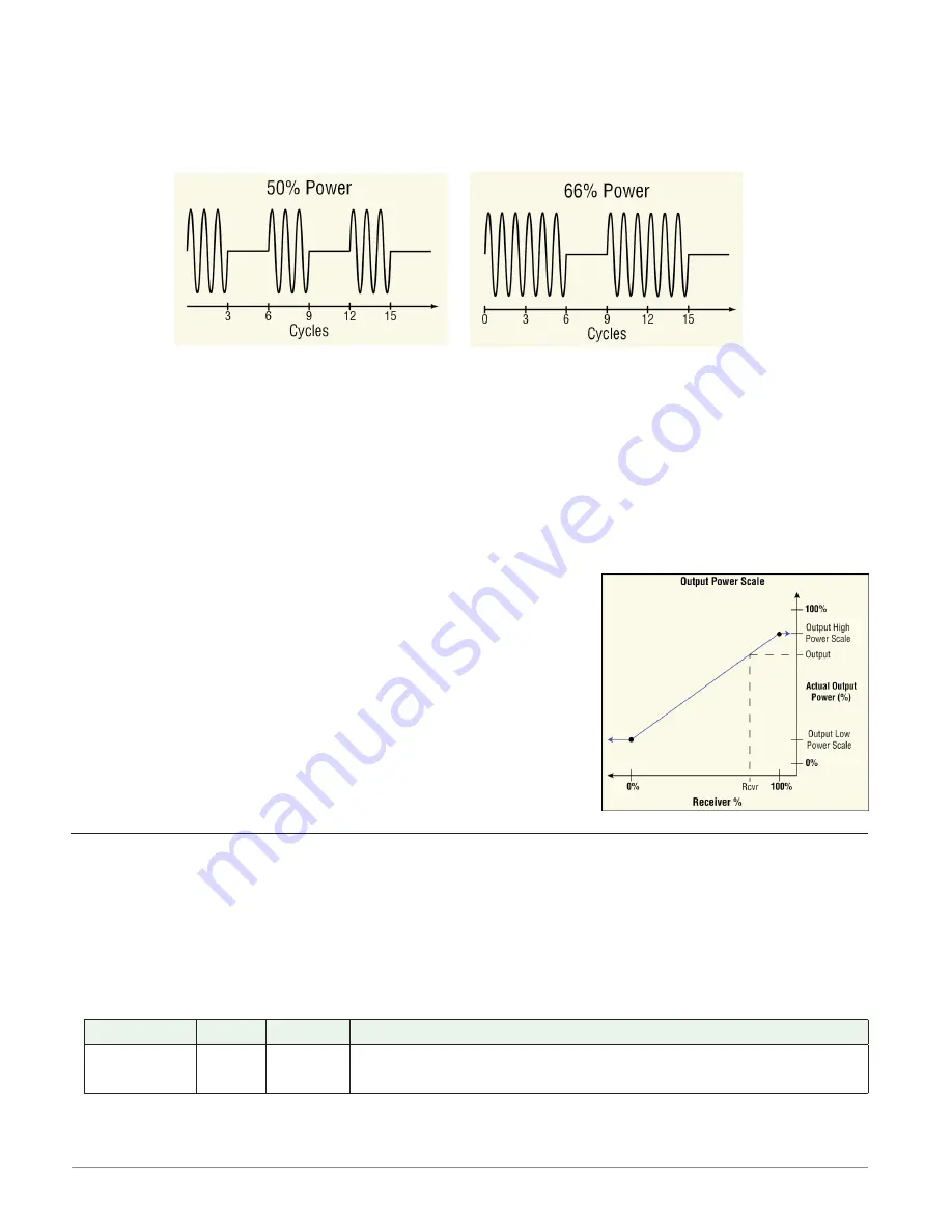
three, and when 50% power is called for, the output is on for three ac cycles and off
for three. This method is appropriate for Solid-State Relays (SSR) or Silicon Controlled
Rectifier (SCR) power data loggers. Do not use a variable time base output to control
electromechanical relays, mercury displacement relays, inductive loads or heaters with
unusual resistance characteristics.
Fixed Time Base
Set the duration of one on-off cycle. This applies when the Time Base Type is set to Fixed
Time Base.
Range: 0.1 to 60.0 seconds
Low Power Scale
Set the minimum power level for the output. When the input equals 0% (off), the output is
equal to the value set here. When the input equals 100% (on), the output is equal to the value
set with High Power Scale. Values between 0% and 100% are scaled proportionally. See the il-
lustration to the right.
Range: 0.0 to 100.0%
High Power Scale
Set the maximum power level for the output. When the input
equals 100% (on), the output is equal to the value set here.
When the input equals 0% (off), the output is equal to the
value set with Output Low Power Scale. Values between 0%
and 100% are scaled proportionally. See the illustration to the
right.
Range:
0.0 to 100.0%
Input Voltage
Use this function to integrate a signal from a field I/O device that provides a high or low volt-
age signal indicating its state. This FB is found on the canvas of the FB diagram. The number
of these FBs that are available depends on the number of digital I/O flex modules installed
and configured as voltage inputs.
Signals
Direction
Label
Type
Function
Transmitter - - - -
Digital
Transmitter is inactive (off) when measured voltage is less
than 2V and active (on) when greater than 3V


