Watlow D4T Data Logger
•
21
•
Chapter 2 Configuration Using Composer
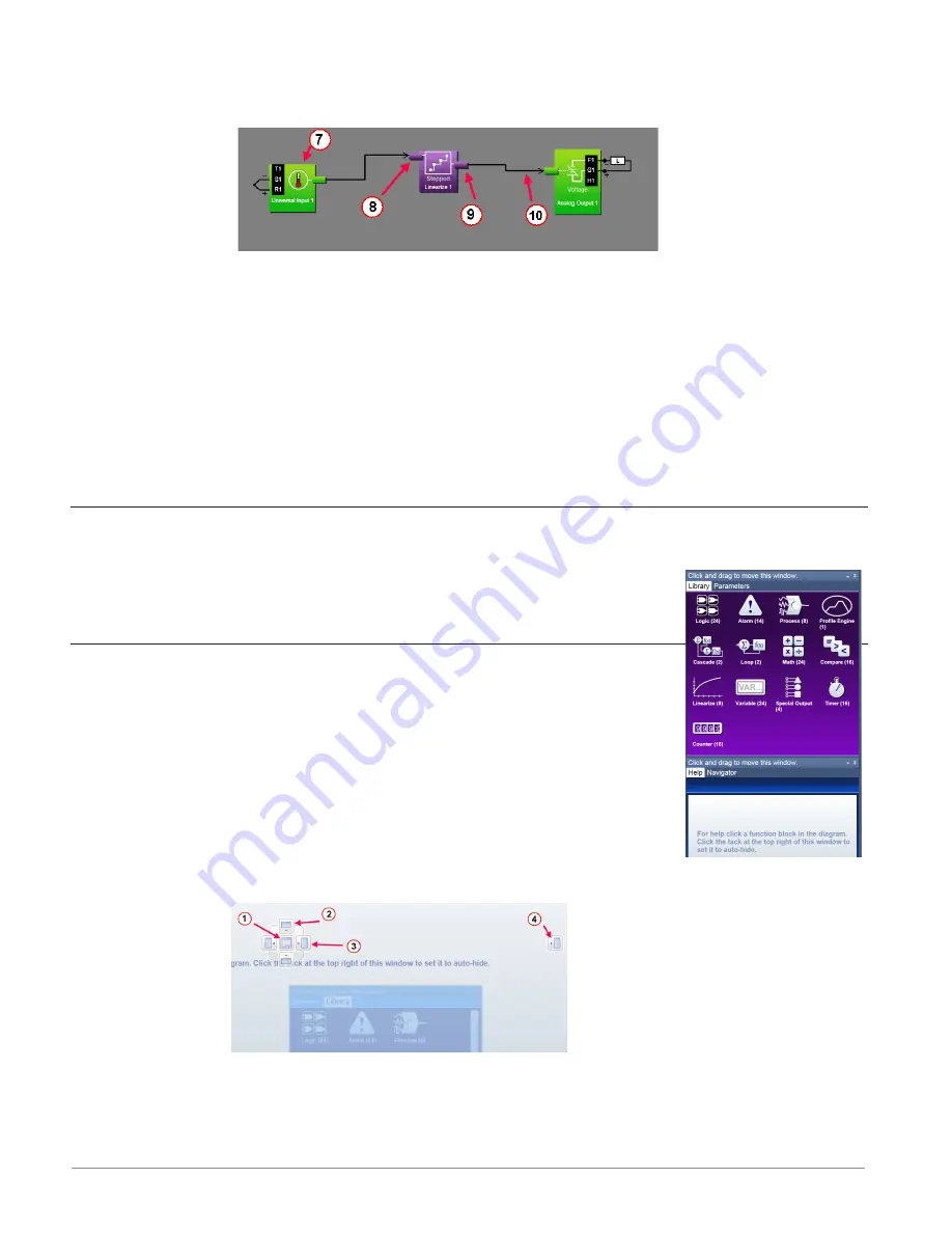
• Allows the user to customize the functionality of the data logger for a specific applica-
tion. Some FBs are interfaces to real-world I/O devices and some serve as the inter-
face to internal functions such as, the compare, logic and math FBs.
⑧
Receiver
• The part of a FB to which a signal can be connected in order to supply data to the
function.
⑨
Transmitter
• The part of a FB from which a signal can be connected in order to carry data to an-
other FB.
⑩
Signal
• A line that represents the connection of data from one FB to another.
Customizing the Function Block Diagram Environment
The Parameter, Help, Library and Navigator windows can be moved from their default loca-
tions to allow a user to maximize the visibility of the FBD diagram. See
the procedures below regarding how to float, hide and dock these win-
dows.
Window Anchor Points
While dragging a window or a grouping of windows to a new docking
location Anchor Points will appear on the screen. The anchor points in
the graphic are numbered corresponding to their associated descriptions
below:
①
Drag the window here to add to the window group.
②
Drag window here to dock above the window group.
e
Drag window here to dock to the right of the window group.
r
Drag window here to dock at the right of the screen.
Getting Started with the Function Block Diagram (FBD)
The basic steps for creating the function block diagram for any application are:


